ANSI Bushing
ANSI Transformer Bushing: Specifications, Application & Selection Handbook
ANSI Transformer Bushing: Specifications, Application & Selection Handbook
SEO Keywords: ANSI transformer bushing, ANSI distribution transformer bushing, ANSI porcelain bushing, spade‑type ANSI bushing, eyebolt bushing ANSI, transformer tank opening dimension, ANSI bushing creepage distance, pad‑mount transformer bushing
Overview of ANSI Transformer Bushing
An ANSI transformer bushing is a critical through‑wall insulating and conductive component built according to ANSI‑IEEE standards (IEEE C57.19.00, IEEE C57.19.01, ANSI C29 series), widely used for oil‑immersed pad‑mount, pole‑mount and three‑phase distribution transformers across North‑American‑standard power grids. It performs two irreplaceable core functions: electrically isolating live transformer winding conductors from grounded metal transformer tanks, and establishing stable low‑resistance electrical transition points between internal transformer leads and external overhead cables or elbow connectors.
Core Functional Benefits
Full Standardized Interchangeability: Unified tank opening diameters, bolt‑circle layouts and imperial thread specifications eliminate custom machining during retrofitting. Matching American flower‑basket spin‑grip nuts or aluminum pressure clamps guarantee reliable oil‑tight sealing with elastomer gaskets.
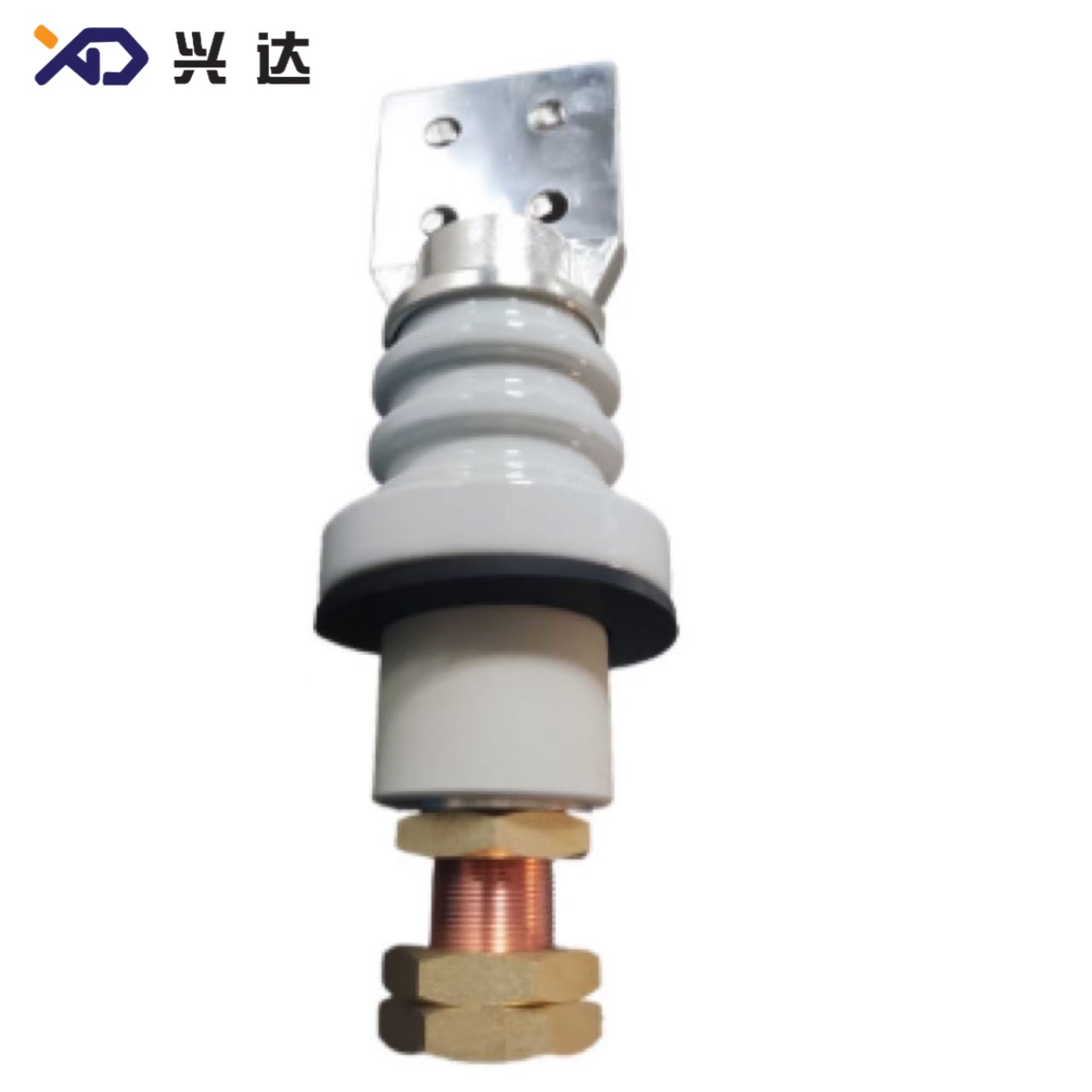
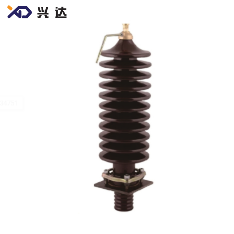
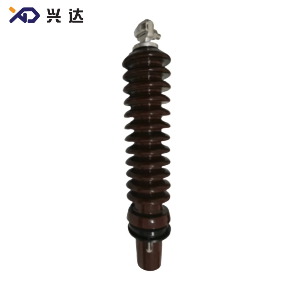
Pollution‑Resistant Shed Profile: Alternating‑diameter porcelain sheds break rainwater cascading flow paths, minimizing surface flash‑over risk under rain, salt spray and industrial dust conditions.
High Mechanical Performance: Designed with defined allowable cantilever load, resisting cable‑pull bending stress, wind vibration and thermal cycling in outdoor field environments.
Broad Rating Portfolio: Complete product series spans voltage from 1.2 kV low‑voltage secondary side up to 34 kV primary‑side medium‑voltage, continuous current ranges 55 A‑3150 A.
Verified Dielectric Performance: Every ANSI‑standard bushing must pass power‑frequency withstand, lightning impulse BIL testing and short‑time thermal test as defined in IEEE standards.
Classification & Reference Dimensional‑Specification Table
ANSI transformer bushings are categorized by rated voltage class, further subdivided by rated continuous current and terminal connection form. Key dimensional terms explained:
Tank opening: Inner hole dimension cut on transformer metal tank shell
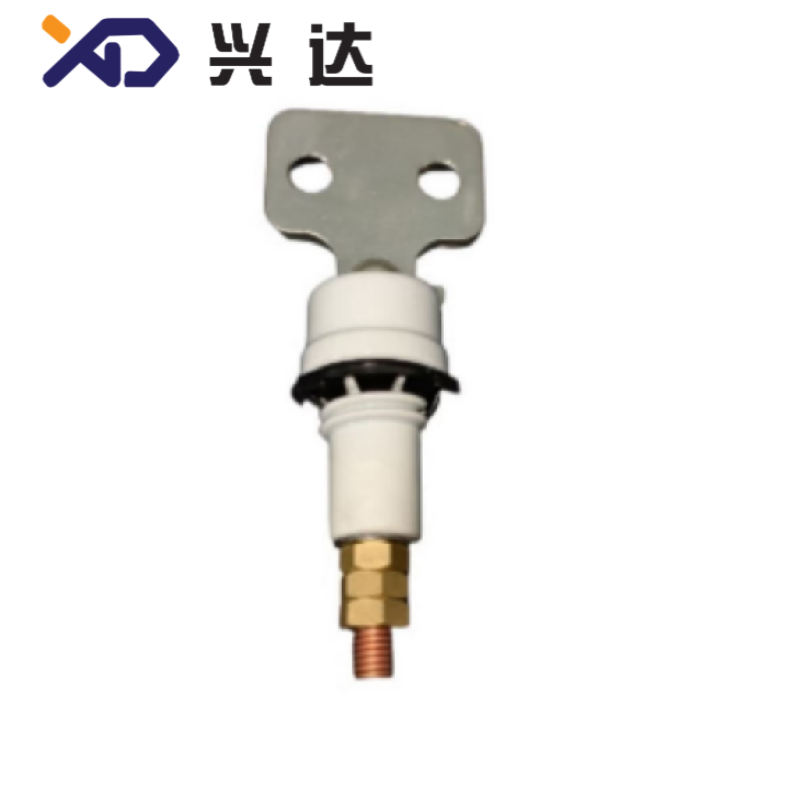
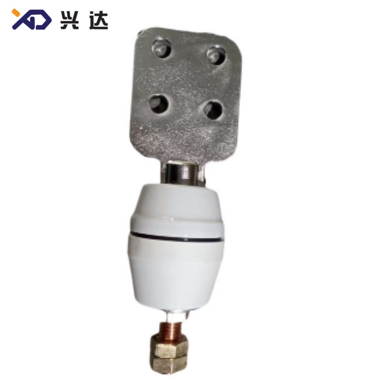
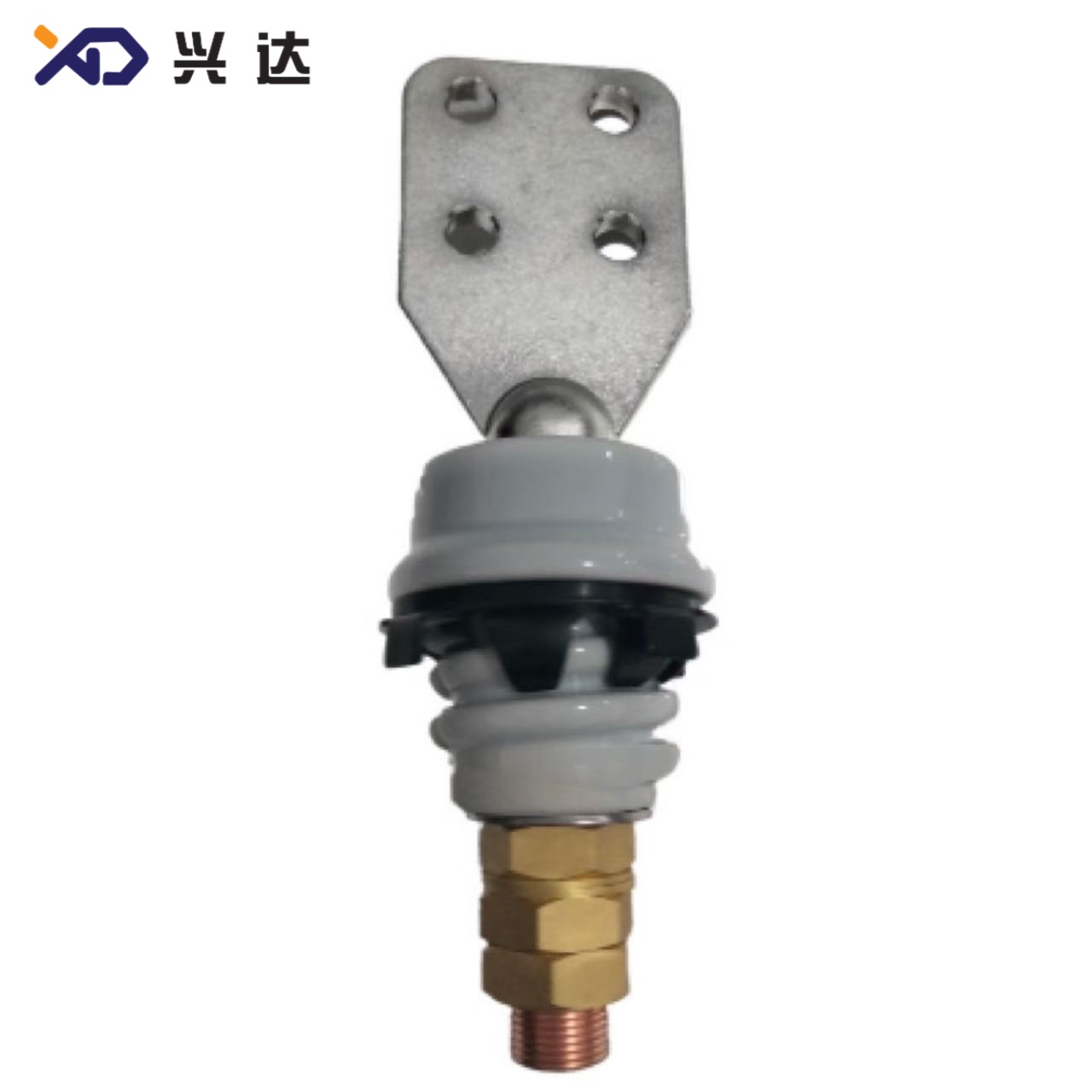
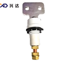
Terminal type: Eyebolt pin / multi‑hole spade flange
Creep distance: Surface insulation creepage length along porcelain shed surface (mm)
| Voltage Class | Rated Current Range | Terminal Options | Typical Tank‑Opening Dimension | Main Application Location |
|---|---|---|---|---|
| 1.2 kV LV | 125 A‑250 A | Eyebolt pin, 2‑hole spade | ∅36.5 mm | Transformer secondary low‑voltage terminals |
| 1.2 kV LV Heavy‑Duty | 417 A‑3150 A | 4‑hole /6‑hole spade flange | ∅71 mm ~ ∅101.6 mm | High‑current secondary output |
| 5 kV MV | 630 A‑4000 A | 4‑hole spade flange | ∅101.6 mm | Intermediate‑voltage distribution transformers |
| 10 kV MV | 800 A‑2000 A | 4‑hole spade flange | ∅101.6 mm | North‑American distribution transformers |
| 15‑34 kV HV | 55 A‑600 A | Eyebolt pin, 2‑hole /4‑hole spade | ∅71 mm‑∅140 mm | Transformer primary high‑voltage incoming side |
Detailed Model Reference Table (Practical Field Specification Data)
| Model No. | Terminal Style | Porcelain Shed Configuration | Tank‑Opening Diameter | Typical Creepage Distance (mm) |
|---|---|---|---|---|
| ANSI‑1.2KV‑125A‑pin | Eyebolt pin | Smooth low‑voltage insulator | ∅36.5 | 25 |
| ANSI‑1.2KV‑250A‑2‑hole | 2‑hole spade flange | Smooth low‑voltage insulator | ∅36.5 | 39 |
| ANSI‑1.2KV‑417A‑4‑hole | 4‑hole spade flange | Smooth low‑voltage insulator | ∅71 | 30 |
| ANSI‑5KV‑1200A‑4‑hole | 4‑hole heavy‑duty spade | Multi‑shed porcelain | ∅101.6 | 250 |
| ANSI‑10KV‑1200A‑4‑hole | 4‑hole spade flange | Multi‑shed porcelain | ∅101.6 | 310 |
| ANSI‑15KV‑55A‑2‑hole | 2‑hole spade / eyebolt | 6‑10 single‑shed | ∅71 | 330 |
| ANSI‑25KV‑417A‑2‑hole | 2‑hole spade flange | 10 single‑shed | ∅71.2 | 523 |
| ANSI‑34KV‑125A‑4‑hole | 4‑hole spade flange | 11 single‑shed | ∅140 | 774.7 |
Critical Parameters for Specifying ANSI Transformer Bushings
- Rated system voltage & BIL level: Confirm nominal transformer primary / secondary voltage, and required Basic Impulse Insulation Level per IEEE standards. Nominal voltage match alone cannot guarantee transient‑overvoltage protection.
- Rated continuous current: Match maximum winding operating current; apply proper safety margin for frequent‑over‑load distribution transformers.
- Terminal connection configuration: Confirm eyebolt pin, hole quantity, hole diameter and flange width dimension “B”.
- Transformer tank opening dimension: Inner hole diameter, mounting bolt‑circle diameter, number and size of mounting holes. Wrong tank opening dimension will make physical installation impossible.
- Required creepage distance: Select creepage length matching local pollution severity (light, medium, heavy, very‑heavy pollution zone) following ANSI C29 insulation rules.
- Allowable cantilever breaking load: For pole‑mount transformers exposed to wind, ice and cable pulling forces.
- Thread specification (Md dimension): Verify whether internal conductor stud uses UNC / UNF imperial thread or metric thread.
- Installation height dimensions (H, h1, h2): h1 = height exposed above tank cover; h2 = immersion depth inside transformer insulating oil. Improper h2 dimension causes insufficient internal oil‑immersed insulation.
Installation Guidance & Preventive Maintenance Best‑Practice
Improper installation accounts for a high share of in‑service ANSI bushing field failures. Key operating rules:
Always install brand‑new oil‑resistant nitrile or viton gaskets; never reuse aged gaskets during bushing replacement.
Apply calibrated torque wrench for spin‑grip nuts and flange bolts. Over‑torque creates invisible micro‑cracks on porcelain; under‑torque results in oil leakage and moisture ingress.
Check shed orientation for high‑voltage multi‑shed bushings, ensure sheds face open‑air outdoor environment.
Do not attempt direct substitution of IEC / DIN‑standard bushings on ANSI‑designed transformer tanks. Divergent tank‑opening, flange‑pattern and thread specifications cannot be compensated only by custom gaskets or simple adapter plates.
For routine maintenance: Perform visual inspection periodically for oil seepage, porcelain crack and surface contamination. Clean polluted insulator sheds for coastal and industrial‑site transformers.
Applicable Industry Standards
- IEEE C57.19.00: General requirements and test procedures for outdoor power apparatus bushings
- IEEE C57.19.01: Performance requirements for power‑transformer bushings
- ANSI C29.9: Wet‑process porcelain insulators for power apparatus
ANSI C84.1: Voltage ratings for electric power systems and equipment
Categories
Contact Us
Contact: Tianjin Delda Trading Co., Ltd
WhatsApp: +86 13662056855
Tel:
E-mail: solomon20210701@tjxddq.com
Add: Unit‑101, Workshop 3, Bozhong Automobile Industrial Park, No.5 Xianghui Road, Intersection of Xianghui Road and Gaoying Road, Beizhakou Town, Jinnan District, Tianjin, China