ANSI Bushing
ANSI Transformer Bushing: Dimensional Reference, Material Selection and Operational Considerations
ANSI Transformer Bushing: Dimensional Reference, Material Selection and Operational Considerations
SEO Keywords: ANSI transformer bushing dimensions, ANSI bushing material options, ANSI porcelain transformer bushing, flower basket nut ANSI bushing, ANSI bushing cantilever load, ANSI transformer bushing creepage requirements, distribution transformer secondary bushing
Introduction
ANSI transformer bushings serve as the critical dielectric barrier and electrical connection point for oil‑filled distribution transformers designed to North‑American IEEE‑ANSI standards. Unlike general‑purpose electrical insulators, these bushings must simultaneously satisfy electrical insulation performance, current‑carrying capacity, mechanical mounting constraints and long‑term oil‑sealing requirements inside transformer tanks. They are widely fitted on pad‑mounted, pole‑mounted and unit‑substation transformers for both primary high‑voltage incoming circuits and secondary low‑voltage output circuits.
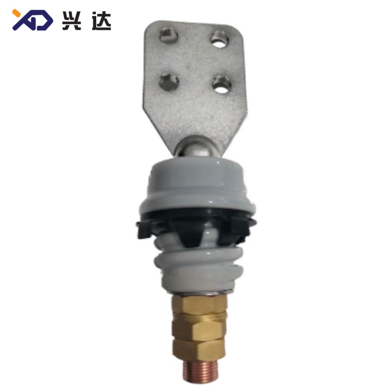
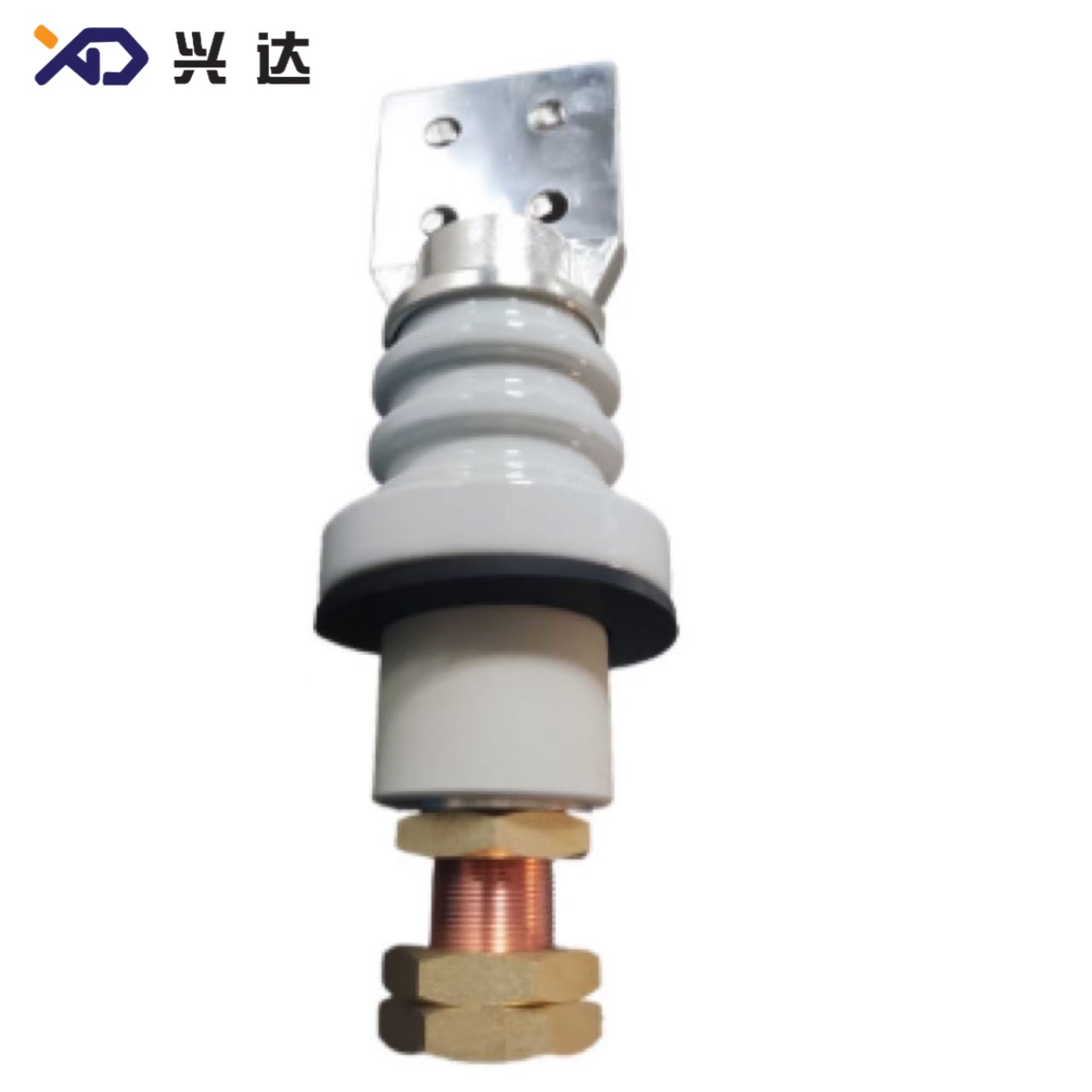
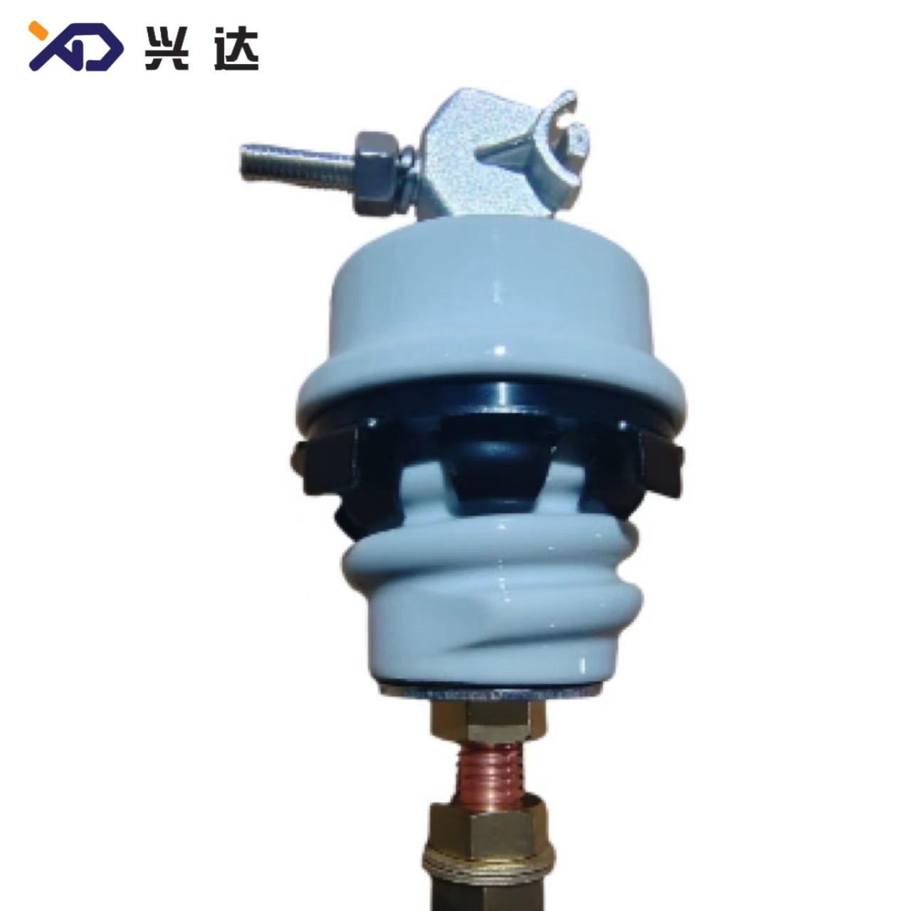
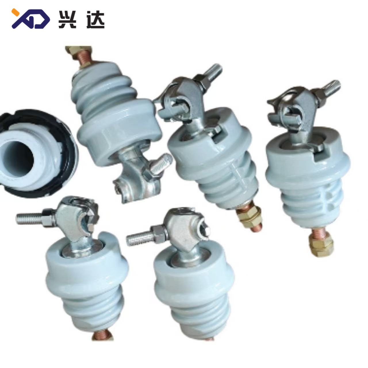
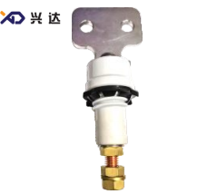
The whole product family spans 1.2 kV low‑voltage secondary ratings up to 34 kV medium‑voltage primary ratings, with continuous current covering 55 A small‑current primary terminals all the way to 3150 A heavy‑duty secondary terminals. Terminal hardware includes eyebolt pin terminals for compact high‑voltage connections, plus single‑hole, two‑hole, four‑hole and six‑hole spade flanges for high‑current secondary circuits. Two major mounting hardware types are applied across the series: American flower‑basket spin‑grip nuts for smaller‑size bushings, and machined aluminum pressure clamps for larger high‑current bushing variants. Insulator materials mainly include glazed wet‑process porcelain and silicone polymer composite, each suited for distinct site environmental conditions.
Material Selection for ANSI Transformer Bushings
Material choice directly influences service life, pollution resistance and total cost of ownership for ANSI bushings. Two mainstream insulator materials are widely adopted in the industry:
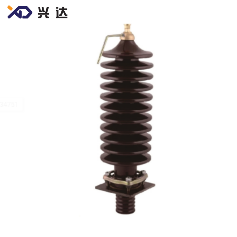
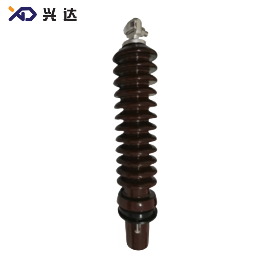
Wet‑Process Glazed Porcelain InsulatorPorcelain is the traditional dominant material for ANSI transformer bushings. The dense glazed surface delivers strong resistance against ultraviolet aging, ozone degradation and transformer‑oil chemical erosion. It maintains stable dielectric performance under long‑term outdoor exposure. Porcelain ANSI bushings are cost‑effective for normal inland, low‑to‑medium pollution utility sites. One known weakness is brittleness: excessive cantilever force or over‑tight mounting torque can create hidden micro‑cracks, which may evolve into oil leakage or dielectric failure over operation cycles.
Silicone Composite Polymer InsulatorComposite ANSI bushings use fiberglass core rods with silicone rubber shed housing. This material offers superior hydrophobic performance, making it ideal for coastal salt‑fog zones, chemical industrial areas and heavy‑pollution locations. Composite insulators weigh significantly less than equivalent‑rating porcelain units, lowering transportation and on‑site handling risks. Drawbacks include higher unit price and potential silicone surface degradation under long‑term severe ultraviolet exposure in tropical regions.
Conductive internal studs and terminal flanges are normally copper or copper‑alloy to keep contact resistance low. Mounting hardware includes steel flower‑basket nuts and aluminum clamps, paired with oil‑resistant elastomer gaskets to realize tank wall sealing.
ANSI Transformer Bushing Complete Specification & Dimensional Reference Table
Dimensional parameters are extracted from standard ANSI bushing engineering drawings. Key field definitions:
Terminal Type: Eyebolt pin / multi‑hole spade flange
Tank Opening: Diameter of cut‑out aperture on transformer metal tank
Shed Configuration: Smooth body for low‑voltage units; single‑shed multi‑rib construction for medium‑voltage models
Creepage Distance: Leakage path length across external insulating surface, measured in millimeters
Full Rating‑Mapping Overview Table
| Rated Voltage | Continuous Current Range | Available Terminal Hardware | Standard Tank Opening (mm) | Typical Mounting Hardware | Application Scenario |
|---|---|---|---|---|---|
| 1.2 kV | 125 A‑250 A | Eyebolt pin, 2‑hole spade | ∅36.5 | Flower‑basket spin‑grip nut | Small‑size distribution transformer secondary |
| 1.2 kV | 417 A‑1200 A | 4‑hole spade flange | ∅71 | Aluminum pressure clamp | Medium‑ampacity secondary output |
| 1.2 kV | 1400 A‑3150 A | 4‑hole / 6‑hole heavy‑duty spade | ∅101.6 | Heavy‑duty aluminum clamp | Large‑capacity transformer secondary terminals |
| 5 kV | 630 A‑4000 A | 4‑hole spade flange | ∅101.6 | Aluminum pressure clamp | Intermediate‑voltage distribution equipment |
| 10 kV | 800 A‑2000 A | 4‑hole spade flange | ∅101.6 | Aluminum pressure clamp | General‑purpose North‑American distribution transformers |
| 15 kV‑18 kV | 55 A‑600 A | Eyebolt pin, 2‑hole /4‑hole spade | ∅71 ~ ∅140 | Flower‑basket nut / aluminum clamp | Primary‑side high‑voltage incoming terminals |
| 25 kV‑34 kV | 55 A‑600 A | Eyebolt pin, 2‑hole /4‑hole spade | ∅92 ~ ∅140 | Aluminum pressure clamp | High‑voltage primary for long‑feed overhead distribution |
Detailed Model‑Level Dimensional Reference
| Model Identifier | Terminal Form | Shed Layout | Tank‑Opening Diameter (mm) | Creepage Distance (mm) |
|---|---|---|---|---|
| ANSI‑1.2KV‑125A‑pin | Eyebolt pin | Smooth LV body | ∅36.5 | 25 |
| ANSI‑1.2KV‑250A‑2‑hole | 2‑hole spade flange | Smooth LV body | ∅36.5 | 39 |
| ANSI‑1.2KV‑417A‑4‑hole | 4‑hole spade flange | Smooth LV body | ∅71 | 30 |
| ANSI‑1.2KV‑2000A‑6‑hole | 6‑hole heavy‑duty spade | Smooth LV body | ∅101.6 | 50 |
| ANSI‑5KV‑630A‑4‑hole | 4‑hole spade flange | Multi‑shed porcelain | ∅101.6 | 250 |
| ANSI‑10KV‑1200A‑4‑hole | 4‑hole spade flange | Multi‑shed porcelain | ∅101.6 | 310 |
| ANSI‑15KV‑55A‑2‑hole | 2‑hole spade / eyebolt | 8‑10 single‑shed | ∅71 | 330 |
| ANSI‑25KV‑417A‑2‑hole | 2‑hole spade flange | 10 single‑shed | ∅71.2 | 523 |
| ANSI‑34KV‑55A‑2‑hole | Eyebolt pin | 11‑15 single‑shed | ∅92 | 774.7 |
| ANSI‑34KV‑125A‑4‑hole | 4‑hole spade flange | 11 single‑shed | ∅140 | 774.7 |
Dimensional Critical Points for ANSI Bushing Deployment
When reviewing drawings and ordering replacement ANSI bushings, several easily‑overlooked dimensional parameters heavily impact field fitness:
h1 (Height above tank surface): This dimension defines how much insulator sits exposed to open‑air environment. Too‑short h1 reduces dry‑arcing distance and raises flash‑over probability; excessive height increases cantilever moment from cable weight and wind load.
h2 (Oil‑immersed depth below tank): This section works inside transformer insulating oil. Insufficient immersion depth degrades internal dielectric clearance; overly long h2 risks physical interference with internal transformer windings or lead assemblies.
Md (Lower stud thread size): ANSI designs commonly use UNC / UNF imperial threads, while some heavy‑current variants adopt metric threads. Mismatched thread cannot assemble and may damage internal conductor connections.
Bolt hole pattern on spade terminal: Hole quantity, hole diameter and center‑to‑center spacing of spade flange mounting holes must match field cable lugs. Non‑matching hole patterns force dangerous on‑site hole re‑drilling.
Tank opening corner radius: Original ANSI drawings specify R3, R5 and other radius values for tank cut‑outs. Sharp corners on transformer tank openings may create local stress concentration and harm bushing sealing performance.
Cantilever Load & Environmental Considerations
Cantilever load rating is a frequently‑neglected mechanical specification for ANSI transformer bushings, especially for pole‑mount transformers. Cantilever load describes the maximum lateral force permitted at the bushing top terminal, caused by overhead cable tension, wind pressure and ice accumulation. If real‑world lateral force exceeds published cantilever limits, porcelain cracking, seal distortion and internal conductor deformation may happen.
For site environmental adaptation:
Normal inland sites: Standard porcelain ANSI bushings with base‑grade creepage distance are sufficient.
Coastal salt‑spray locations: Specify extended creepage distance or silicone composite‑type ANSI bushings.
Heavy industrial pollution zones: Increase creepage class and arrange periodic surface cleaning maintenance schedules.
Inspection & Acceptance Checklist for New ANSI Bushings
Before installation of new ANSI‑standard transformer bushings, complete these acceptance checks:
Cross‑check model marking against specification sheet: rated voltage, rated continuous current and terminal configuration.
Visual inspection: Look for porcelain chips, cracks, glaze defects, or composite housing scratches and tearing.
Verify all critical dimensions: tank opening fit, spade‑flange hole layout, stud thread Md, h1 and h2 heights.
Inspect sealing accessories: Confirm matching flower‑basket nut or aluminum clamp and intact, undamaged oil‑resistant gaskets are available.
Confirm test documentation referencing IEEE C57.19 standards for dielectric, thermal and mechanical performance.
Common Installation Mistakes to Avoid
Re‑using old gaskets: Aged gaskets lose elasticity, and become the top cause of transformer oil leakage after bushing replacement. Always fit brand‑new gaskets.
Overtightening flower‑basket nuts or clamp bolts: Without torque‑wrench control, porcelain bushings can develop invisible internal cracks.
Forced mis‑alignment assembly: Never hammer or pry to force a bushing into a non‑matching tank opening; re‑verify dimensional drawings instead.
Mixing ANSI and IEC‑DIN bushing components: Even if adapter plates physically cover hole‑pattern differences, insulation coordination and cantilever safety margins cannot be guaranteed.
Incorrect shed orientation for multi‑shed high‑voltage bushings: Sheds must face outward toward atmosphere to realize designed creepage protection.
Relevant Industry Standards
IEEE C57.19.00: General requirements and test procedures for outdoor power apparatus bushings
IEEE C57.19.01: Performance specifications for power transformer bushings
ANSI C29.9: Wet‑process porcelain insulators for power equipment
IEEE C57.12.00: General requirements for liquid‑immersed distribution transformers
Categories
Contact Us
Contact: Tianjin Delda Trading Co., Ltd
WhatsApp: +86 13662056855
Tel:
E-mail: solomon20210701@tjxddq.com
Add: Unit‑101, Workshop 3, Bozhong Automobile Industrial Park, No.5 Xianghui Road, Intersection of Xianghui Road and Gaoying Road, Beizhakou Town, Jinnan District, Tianjin, China