DIN Bushing
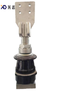
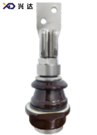
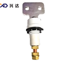
1‑3KV/1000‑4500A DIN Bushing for DIN‑Standard Oil‑Immersed Distribution Transformers
1‑3KV/1000‑4500A DIN Bushing: Definition, Structural Features, Specifications, Advantages, Application, Selection and Maintenance Guide
1. Introduction
This article delivers in‑depth, industry‑oriented technical documentation covering definition, DIN‑standard background, mechanical structure, full‑range model introduction, performance advantages, complete dimension specification table, multi‑scene application scope, detailed selection workflow, installation requirements, commissioning checks, periodic maintenance rules, typical fault analysis, custom‑dimension possibilities, and cross‑standard comparison. It serves as a practical reference material for transformer design engineers, procurement specialists, production technicians, substation operation‑maintenance staff, and international power‑equipment exporters.
2. Definition and Core Function of 1‑3KV/1000‑4500A DIN Bushing
It is important to note that “DIN bushing” refers to the product series complying with German DIN power‑equipment standards for transformer accessories. All dimensional systems, thread specifications, mounting‑hole arrangements and performance test requirements follow DIN‑series industrial norms, to achieve mechanical interchangeability among compliant components across different suppliers in European power‑equipment supply chains.
3. DIN Standard Background for Low‑Voltage High‑Current Transformer Bushings
4. Structural Composition & Detailed Structural Features
4.1 Insulating Housing with Single‑Shed Shield
4.2 Conductive Conductor Assembly
4.3 Top Terminal Plate Structure
- 1000A model: 2‑M10 terminal bolt layout. Corresponding dimension parameters a1, a2, a3, a4 define terminal plate outline and bolt‑hole positions.
- 2000A‑4500A models: 4‑M16 terminal bolt layout. Larger terminal‑plate size and more bolt points can disperse contact pressure, reduce contact resistance, and restrain temperature rise under high‑current operation.
4.4 Tank‑Mounting and Sealing Structure
Dimensions of opening of tank defines tank cut‑out geometry, including d0, d2, d3, ΦS and related positional dimensions. For installation, 10*10 square‑steel auxiliary fitting can be applied for auxiliary positioning and fastening. Sealing gaskets are placed between bushing flange surface and transformer tank outer wall, to realize oil‑tight sealing and prevent transformer oil leakage.- H: overall total height of bushing
- h1, h2, h3, h4: multi‑section installation and structural height dimensions
- Md: bottom fastening thread specification
- d1, d2, d3: diameter parameters of insulator and mounting parts
- S, S1: mounting hole positional dimensions for tank‑side fixing
- h1: arcing distance
- creepage distance: surface creepage distance
- weight: unit weight of each model
5. Full Model Range Overview
- DIN‑1/1000 (XD.1000.1.DIN)Rated current 1000 A, rated voltage 1‑3 kV. Adopts 2‑M10 top terminal layout. Compact overall dimension. Suitable for low‑voltage terminals of small‑and‑medium‑capacity DIN‑standard distribution transformers, light‑load industrial power‑supply transformers. Unit weight 5.5 kg.
- DIN‑1/2000 (XD.2000.1.DIN)Rated current 2000 A, rated voltage 1‑3 kV. Upgrade to 4‑M16 multi‑bolt terminal structure. Increased overall height and terminal‑plate size. Applied for medium‑capacity distribution transformers under common industrial‑distribution working conditions. Unit weight 12 kg.
- DIN‑3/1500 (XD.3150.1.DIN)Rated current 3150 A, rated voltage 1‑3 kV. Heavy‑current intermediate model in product series. Optimized conductive cross‑section and terminal‑plate mechanical strength. Widely used for medium‑large‑capacity European‑spec distribution transformers. Unit weight 16.5 kg.
- DIN‑3/1000 (XD.1000.3.DIN)Rated current 1000 A, rated voltage 1‑3 kV. Another variant for 1000A application scenarios, with adjusted overall height parameters, for transformer projects requiring modified installation height constraints. Unit weight 6.5 kg.
- DIN‑3/2000 (XD.2000.3.DIN)Rated current 2000 A, rated voltage 1‑3 kV. 2000A variant with adjusted height dimension, matches transformer designs with different internal space limits. Unit weight 13.5 kg.
- DIN‑3/3150 (XD.3150.3.DIN)Rated current 3150 A, rated voltage 1‑3 kV. High‑performance 3150A model with larger overall dimension, for heavy‑duty continuous‑load transformer low‑voltage terminals. Unit weight 18.7 kg.
- DIN‑3/4500 (XD.4500.3.DIN)Rated current 4500 A, rated voltage 1‑3 kV. Maximum‑current‑rating model within this whole series. Largest terminal‑plate dimension, thickened conductive parts, enhanced mechanical structure. For large‑capacity power transformers, main low‑voltage output terminals of heavy‑load industrial transformers. Unit weight 33.5 kg.
All seven models use single‑shed (single shield) insulator structure. The difference between various models mainly reflects on overall height H, sub‑height dimensions (h1, h2, h3, h4), terminal‑plate size, terminal‑bolt layout, Md thread specification, tank‑opening related dimensions, arcing distance, creepage distance and unit weight.
6. Core Technical Advantages of 1‑3KV/1000‑4500A DIN Bushing
- Full DIN‑Standard Compliance: Designed and dimensioned following German DIN power‑equipment standards, fully compatible with European‑spec oil‑immersed transformers, ideal for transformer manufacturing and spare‑part supply targeting European market and other regions adopting DIN specifications.
- Ultra‑Wide Heavy‑Current Coverage: Continuous rated current ranges from 1000 A up to 4500 A, covers low‑voltage terminal requirements for small‑medium‑large capacity DIN‑standard transformers, one series satisfies diversified ampere‑grade demands.
- Graded Terminal‑Bolt Layout: Scientifically differentiated terminal‑connection design: 2‑M10 layout for 1000A, 4‑M16 layout for ≥2000A. More contact bolts for higher‑current models effectively reduce contact resistance and suppress temperature rise under long‑term heavy‑load operation.
- Complete and Standardized Dimensional System: Every model defines clear overall height, sub‑section height, fastening thread Md, terminal‑plate size, tank‑opening cut‑out dimension, arcing distance and creepage distance. Transformer designers can directly select models according to parameter sheets, reducing repeated drawing‑design workload.
- Reliable Tank‑Sealing Performance: Cooperates with gaskets and optional 10*10 square‑steel auxiliary fitting, achieves stable oil‑tight sealing effect on transformer tank wall, lowers risk of transformer oil leakage at bushing mounting position.
- Single‑Shed Insulator Structure: Optimized single‑shed design provides sufficient creepage distance, fits indoor and mild‑pollution outdoor operating environments; insulator material features good oil‑resistance, anti‑aging and mechanical‑shock‑resistant performance.
- Flexible Customization Support: Apart from standard stock models, non‑standard special dimensions can be customized according to project‑specific requirements, adapting to transformer‑retrofit scenarios and special new‑build equipment with unique structural constraints.
- Convenient Installation and Maintenance: Standardized mounting‑hole and thread specifications facilitate on‑site assembly work. Modular‑style assembly structure simplifies later‑period disassembly and spare‑part replacement during transformer overhaul.
Stable Temperature‑Rise Performance: Each current‑grade model is matched with reasonable conductive cross‑section area. Under rated continuous‑current operation, temperature‑rise value stays within DIN‑standard allowable range, avoiding overheating‑caused equipment failures.
7. Complete Technical Specification Table
Table: 1‑3KV/1000‑4500A DIN Bushing Technical & External Dimensions
| Code | Model | H | h2 | h3 | h4 | a3×a4 | a1×a2 | d4 | t | Md | d1 | d2 | d3 | S | S1 | d0 Tank opening | h1 arcing distance | creep distance | shield shed type | weight(kg) |
|---|---|---|---|---|---|---|---|---|---|---|---|---|---|---|---|---|---|---|---|---|
| XD.1000.1.DIN | DIN‑1/1000 | 324 | 58 | 17 | 4‑8 | 60×60 | 26×26 | Φ10 | 14 | M30×2 | 90 | 110 | 90 | ‑ | 50 | 56 | 57 | 75 | single shed | 5.5 |
| XD.2000.1.DIN | DIN‑1/2000 | 405 | 63 | 22 | 6‑10 | 100×100 | 50×40 | Φ14 | 15 | M42×3 | 104 | 125 | 105 | ‑ | 110 | 60 | 58 | 70 | single shed | 12 |
| XD.3150.1.DIN | DIN‑3/1500 | 434 | 68 | 27 | 6‑10 | 120×120 | 60×40 | Φ14 | 15 | M48×3 | 125 | 125 | 125 | ‑ | 110 | 70 | 57 | 75 | single shed | 16.5 |
| XD.1000.3.DIN | DIN‑3/1000 | 372 | 78 | 17 | 4‑8 | 60×60 | 26×26 | Φ10 | 14 | M30×2 | 110 | 125 | 90 | ‑ | 50 | 56 | 87 | 120 | single shed | 6.5 |
| XD.2000.3.DIN | DIN‑3/2000 | 460 | 83 | 22 | 6‑10 | 100×100 | 50×40 | Φ14 | 15 | M42×3 | 125 | 150 | 105 | ‑ | 60 | 90 | 88 | 120 | single shed | 13.5 |
| XD.3150.3.DIN | DIN‑3/3150 | 495 | 88 | 27 | 6‑10 | 120×120 | 60×40 | Φ14 | 18 | M48×3 | 145 | 125 | 110 | ‑ | 160 | 119 | 88 | 120 | single shed | 18.7 |
| XD.4500.3.DIN | DIN‑3/4500 | 560 | 101 | 30 | 6‑12 | 150×150 | 70×70 | Φ20 | 20 | M55×3 | 175 | 160 | 150 | ‑ | 160 | 100 | 95 | 125 | single shed | 33.5 |
Notes:
- All above‑listed data are standard reference dimensions for general‑industry application.
- Non‑standard special dimensions can be customized according to end‑user project requirements.
- 1000A models adopt 2‑M10 terminal bolt layout; models ≥2000A adopt 4‑M16 terminal bolt layout.
- 10*10 square‑steel auxiliary fitting can be used for tank‑mounting auxiliary positioning.
8. Conclusion
Categories
Contact Us
Contact: Tianjin Delda Trading Co., Ltd
WhatsApp: +86 13662056855
Tel:
E-mail: solomon20210701@tjxddq.com
Add: Unit‑101, Workshop 3, Bozhong Automobile Industrial Park, No.5 Xianghui Road, Intersection of Xianghui Road and Gaoying Road, Beizhakou Town, Jinnan District, Tianjin, China