DIN Bushing
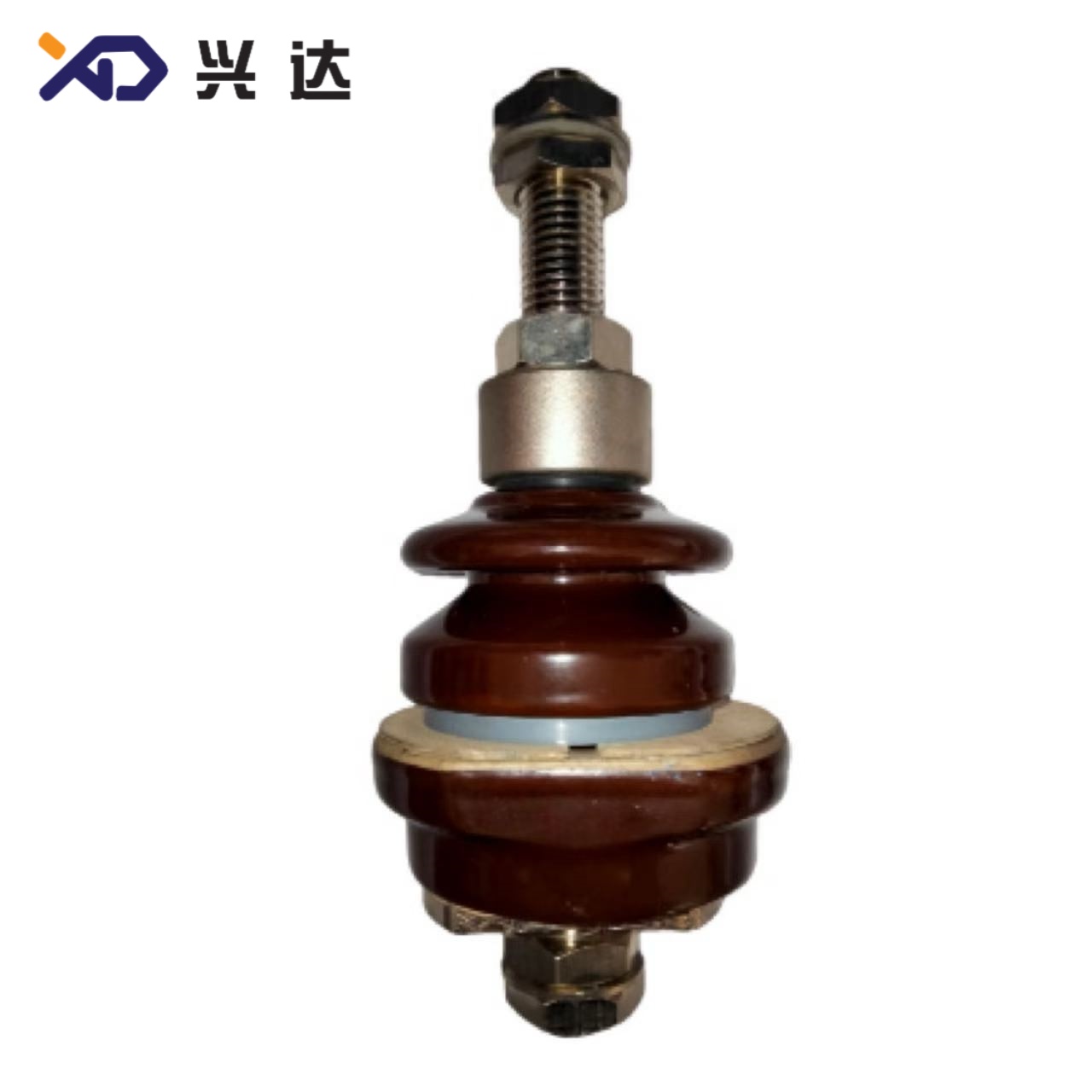
DIN Transformer Bushing: Complete Guide to DIN‑Standard Bushings for Oil‑Filled Transformers
DIN Transformer Bushing: Complete Guide to DIN‑Standard Bushings for Oil‑Filled Transformers
Introduction to DIN Bushing
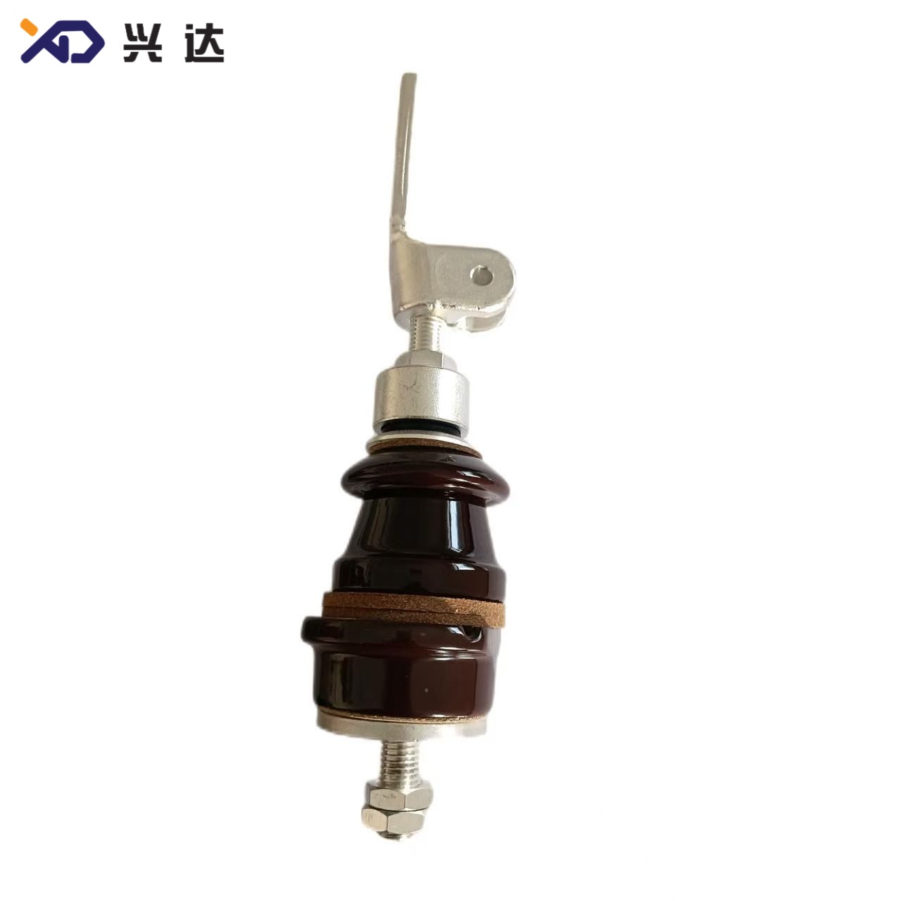
A DIN bushing, also named DIN‑standard transformer bushing, is a critical insulating pass‑through component widely deployed on oil‑immersed distribution transformers and power transformers across Europe, Middle East, Africa, and global transformer retrofit projectsZeeyi Elec.... Derived from historic German DIN specifications (DIN 42530, DIN 42531, DIN 42532, DIN 42533), this component family is now harmonized under modern IEC 60137 and EN 50180 standards for medium‑voltage transformer equipmentNJREC.
The core purpose of a DIN transformer bushing is three‑fold: first, to provide high‑voltage electrical insulation for live conductors passing through the grounded metal transformer tank wall or tank cover; second, to maintain oil‑tight sealing so transformer oil cannot leak out and ambient moisture, dust cannot penetrate inside the transformer tank; third, to offer stable mechanical connection points for internal transformer winding leads and external overhead lines, bus‑bars or cable terminals.
DIN bushings cover a broad rating spectrum: nominal voltage ranges from low‑voltage 1 kV / 3 kV up to medium‑voltage 12 kV, 24 kV, 36 kV, even 52 kV; rated continuous current spans 250 A, 400 A, 630 A up to 1000 A, 2000 A, 3150 A and 4500 A for heavy‑duty transformer applicationsNJREC. Two major construction categories exist: low‑voltage DIN bushings (1‑3 kV for transformer LV side), and medium‑voltage DIN bushings (12‑36 kV for HV side). Common mechanical mounting designs include flange‑type, threaded stem type, cable‑through draw‑lead style, and high‑current flag‑terminal variants for large‑capacity transformersZeeyi Elec....
Key search terms for this article: DIN bushing, DIN transformer bushing, DIN standard bushing, porcelain DIN bushing, transformer tank bushing, DIN 42530 bushing, medium voltage DIN bushing, oil filled transformer bushing, DIN bushing dimensions, DIN bushing creepage distance.
Core Working Principles of DIN‑Standard Transformer Bushing
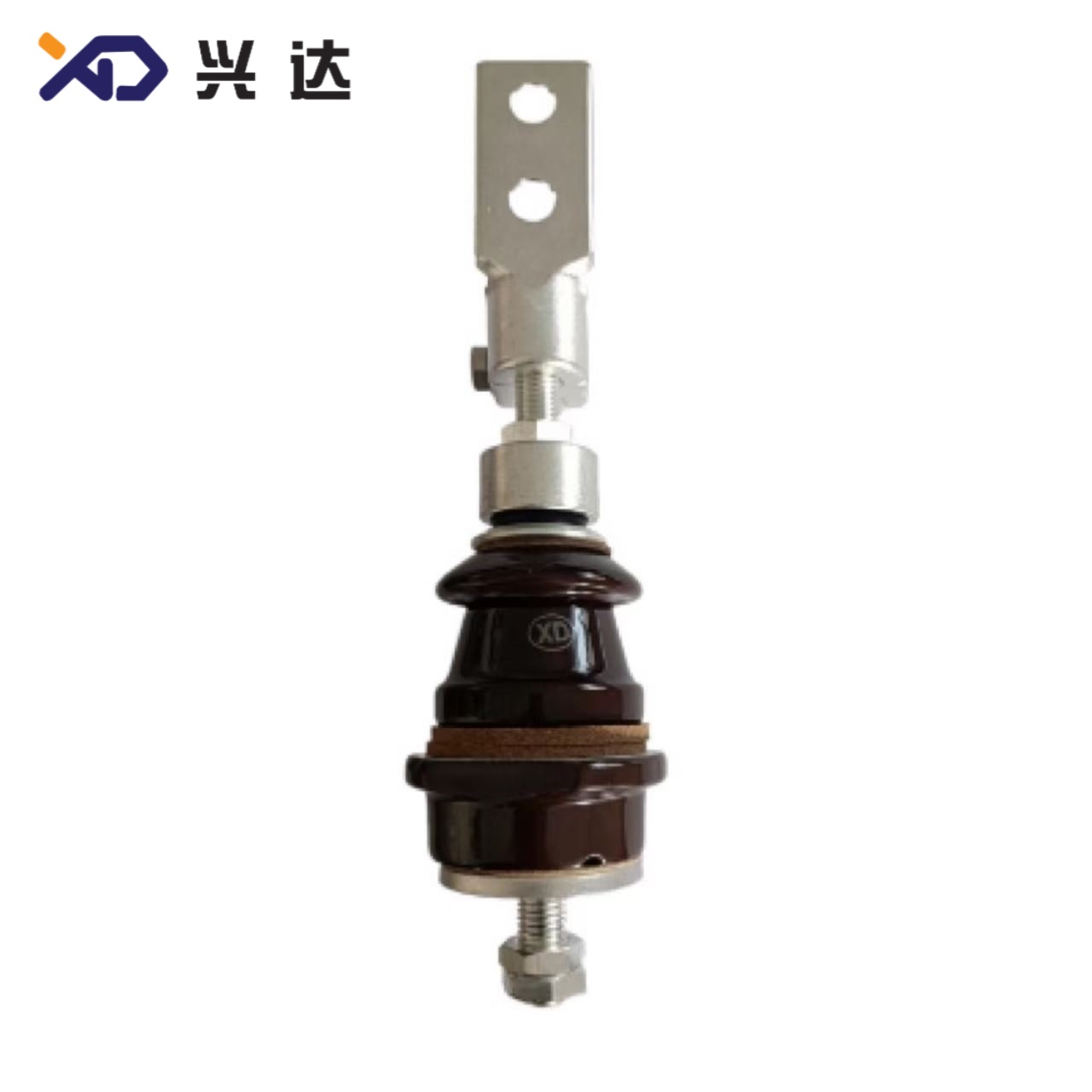
Understanding how a DIN bushing operates helps electrical engineers, transformer designers and procurement specialists make correct component selection. Each standard DIN bushing assembly consists of four fundamental sub‑assemblies: central conductive stem, insulating body (porcelain or composite sheds), metal mounting flange / clamping hardware, and dual‑end connection terminals (internal tank side, external air side).
Electrical insulation function: The glazed porcelain insulator body separates live copper conductor from grounded transformer tank. External sheds (umbrella‑shaped skirts) extend surface leakage path, defined as creepage distance, to resist surface flash‑over under rain, fog, salt contamination or industrial pollution conditions. Dry‑arcing distance, also called dry arcing distance, is the shortest air gap across the insulator between live terminal and grounded flange, determining impulse withstand capability in dry atmospheric conditionsZeeyi Elec....
Oil‑tight sealing: Gasket sets between bushing flange and transformer tank opening create compression sealing. Typical gasket thickness allowance for DIN‑series bushings is 4 ~ 8 mm, to absorb minor tank surface flatness deviation while preventing oil leakage.
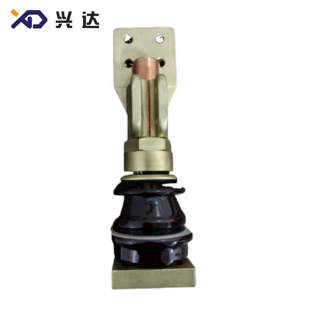
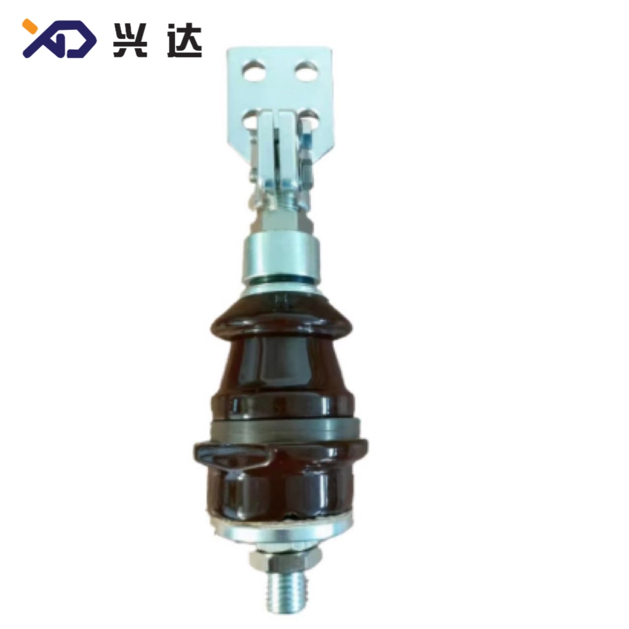
Current conduction: Solid copper or brass central stem transfers rated load current from transformer internal windings out to external power grid connections. High‑current DIN bushings above 1000 A adopt flag‑type multi‑hole connection plates instead of simple threaded studs for higher contact area and lower heat rise.
Mechanical interchangeability: This is the most prominent advantage of DIN bushing series. Tank cut‑out opening sizes, flange mounting hole layout, main thread sizes (Md) are standardized by voltage‑current rating. A DIN bushing from different manufacturers can fit the same transformer tank opening without re‑working tank metalwork, which drastically simplifies new transformer assembly and field retrofit replacement workZeeyi Elec....
Note: Custom modified DIN bushings are widely available. Manufacturers can adjust overall height H, thread specifications, shed quantity, creepage distance and terminal configurations to meet non‑standard transformer design requirements, while keeping standard tank‑opening dimensions unchanged for interchangeability.
Main Advantages of Using DIN‑Standard Transformer Bushings
Compared to non‑standard custom bushings or ANSI‑series North‑American style transformer bushings, DIN bushing solutions deliver multiple practical benefits for transformer OEMs, utility operators and maintenance teamsZeeyi Elec...:
Full dimensional interchangeability: Standardized tank opening diameters, mounting hole patterns and main thread Md eliminate re‑engineering work. Spare‑part inventory cost reduces for power utilities, as one spare DIN bushing can fit multiple transformer models from different manufacturers.
Broad rating coverage: Complete product portfolio covers low‑voltage 1‑3 kV (250 A‑630 A) up to medium‑voltage 12 kV, 24 kV, 36 kV (250 A‑4500 A). Both small distribution transformers and medium‑size power transformers can adopt DIN bushing platform.
Strong pollution‑resistance performance: Multi‑shed porcelain insulator design supports extended creepage distance options. Users can select 2‑shed, 3‑shed, 4‑shed or up to 8‑9 umbrella‑shed configurations for coastal, heavy industrial pollution environments to satisfy IEC 60815 pollution‑class requirementsZeeyi Elec....
Multiple mechanical connection options: Threaded stud terminals for low‑to‑medium current; flag‑plate terminals for high‑current ratings ≥ 1000 A; draw‑lead cable‑through structure for 12‑36 kV installation variants.
Proven long‑term field reliability: Brown‑glazed electrical porcelain insulator material provides excellent weather resistance, ultraviolet stability and dielectric strength for decades of outdoor operation on oil‑filled transformers.
Flexible customization baseline: While maintaining standard tank‑opening dimensions, designers can adjust total height H, internal stem length h3, external connection hardware, plating (tin‑plated copper terminals) for special project requirements.
DIN Transformer Bushing Classification
DIN‑standard transformer bushings can be grouped by rated voltage class, rated current and mechanical construction form:
1. Low‑Voltage DIN Bushing (1 kV ~ 3 kV)
Typical models: DIN‑1/250, DIN‑1/400, DIN‑1/630, DIN‑1/1000, DIN‑1/2000, DIN‑1/3150, DIN‑1/4500. Application: Low‑voltage side of oil‑immersed distribution transformers. Small‑size compact porcelain body, threaded top and bottom stem connections. 10×10 mm square steel anti‑rotation feature is commonly designed on flange part to stop bushing spinning during torque tightening.
2. Medium‑Voltage Threaded‑Stem DIN Bushing (12 kV ~ 36 kV, 250 A‑630 A)
Typical models: DIN‑12/250, DIN‑12/630, DIN‑24/250, DIN‑24/630, DIN‑36/250. Application: HV side of distribution transformers. Threaded Md main stem connection, multi‑shed porcelain insulators for outdoor service. Two‑end threaded connection style for rigid bolt assembly inside transformer tank.
3. Draw‑Lead / Cable‑Through DIN Bushing (12 kV‑36 kV, 250‑630 A)
Also called cable‑through DIN bushing, this variant is equipped with bending draw‑lead tube for internal winding lead routing. It is widely used when transformer internal lead layout requires offset conductor routing inside tank.
4. High‑Current DIN Bushing (1‑36 kV, ≥ 1000 A up to 4500 A)
Typical models: DIN‑1/1000, DIN‑12/1000, DIN‑24/2000, DIN‑3/3150. Feature: Flag‑type multi‑hole copper connection plates replace simple threaded studs. Mounting flange adopts multi‑bolt hole layout (2‑M10, 4‑M16 etc.) for larger mechanical load and high‑current heat dissipation.
DIN Bushing Technical Specifications & Dimension Tables
All dimension units: millimeter (mm). Data extracted from conventional standard DIN‑series transformer bushing product ranges; custom modified dimensions are available upon project request.
Table 1: 1 ~ 3 kV Low‑Voltage DIN Transformer Bushing Core Parameters
表格
| Model | Rated Voltage(kV) | Rated Current(A) | Main Thread Md | Typical Tank Opening d0 (mm) | Notes |
|---|---|---|---|---|---|
| DIN‑1/250 | 1‑3 | 250 | M12×1.75 | 70 | compact LV bushing |
| DIN‑1/400 | 1‑3 | 400 | M16×2.0 | 70 | |
| DIN‑1/630 | 1‑3 | 630 | M20×2.5 | 87.5 | widely‑used LV transformer bushing |
| DIN‑1/1000 | 1‑3 | 1000 | M30×2.0 | 103 | flag‑terminal optional |
| DIN‑1/2000 | 1‑3 | 2000 | M42×3 | 125 | high‑current type |
| DIN‑1/3150 | 1‑3 | 3150 | M48×3 | 125 | flag‑plate connection |
Table 2: 12 ~ 36 kV DIN Cable‑Through / Draw‑Lead Transformer Bushing (250 A ~ 630 A)
表格
| Model | H Total Height(mm) | h2(mm) | h3(mm) | Md Thread | d1(mm) | d0 Tank Opening(mm) | Dry‑arcing h1(mm) | Creepage Distance(mm) | Shed Configuration | Weight(kg) |
|---|---|---|---|---|---|---|---|---|---|---|
| DIN‑12/250 | 371 | 254 | 59 | M12×1.75 | 140 | 78 | 175 | 300 | 2 single‑shed | 5.0 |
| DIN‑12/630 | 403 | 254 | 59 | M20×2.5 | 150 | 92 | 175 | 310 | 2 single‑shed | 7.1 |
| DIN‑24/250 | 461 | 344 | 74 | M12×1.75 | 145 | 78 | 250 | 440 | 3 single‑shed | 6.8 |
| DIN‑24/630 | 493 | 344 | 74 | M20×2.5 | 160 | 92 | 250 | 460 | 3 single‑shed | 9.3 |
| DIN‑36/250 | 561 | 444 | 74 | M12×1.75 | 155 | 92 | 355 | 670 | 4 single‑shed | 12.0 |
Table 3: High‑Current DIN Transformer Bushing (≥ 1000 A) Key Dimensions
表格
| Model | Rated Voltage(kV) | Rated Current(A) | Main Thread Md | Tank Opening d0(mm) | Typical Dry‑arcing h1(mm) | Shed Type |
|---|---|---|---|---|---|---|
| DIN‑1/1000 | 1‑3 | 1000 | M30×2.0 | 103 | 57 | 1 single‑shed |
| DIN‑3/3150 | 1‑3 | 3150 | M48×3 | 125 | 89 | 1 single‑shed |
| DIN‑12/1000 | 12 | 1000 | M30×2.0 | 108 | 340 | 2 single‑shed |
| DIN‑24/2000 | 24 | 2000 | M42×3 | 131 | 346 | 3 single‑shed |
Definition of dimension symbols for DIN bushing drawings:
H: Overall total height of complete bushing assembly
h1: Dry‑arcing distance (air side insulation distance)
h2: Oil‑side height (inside transformer tank)
h3: Bottom stem extension length below tank inner surface
Md: Main connection thread dimension
d0: Transformer tank opening diameter (critical interchangeability dimension)
Creepage distance: Surface leakage path length over porcelain shed surfaces.
DIN Bushing Selection Guide for Transformer Engineers
When specifying DIN‑standard transformer bushings for new transformers or retrofit replacement projects, follow these critical check‑points:
Confirm rated voltage and rated continuous current match transformer winding nominal parameters. Do not select bushing current lower than transformer nominal load current; consider overload capability margin for distribution transformers.
Match tank opening d0 dimension: This parameter controls mechanical fit. Even if voltage‑rating matches, wrong d0 value will make installation impossible. For replacement jobs, always measure existing transformer tank hole before ordering spare DIN bushing.
Calculate required creepage distance against site pollution class following IEC 60815. Rural light‑pollution sites can adopt base‑standard creepage; coastal salt‑fog or heavy industrial pollution locations need higher creepage versions with increased shed quantity (4‑shed, 8‑shed, 9‑shed options are available for DIN‑36 kV‑250 A).
Select correct connection style:
Threaded stud terminals for current ≤ 630 A;
Flag‑plate multi‑hole terminals for 1000 A and above high‑current applications;
Draw‑lead cable‑through DIN bushing if transformer internal winding lead needs offset bending routing.
Verify mounting gasket compression allowance: standard DIN bushing requires gasket compression range of 4‑8 mm to guarantee oil‑tight sealing. Tank cover flatness should be controlled to avoid oil‑leak risk.
Evaluate customization necessity: Special total height H modification, tin‑plated copper stems, special thread size or non‑standard shed profile can be ordered, while keep d0 tank‑opening unchanged to preserve interchangeability.
Common Installation & Operation Notes for DIN‑Standard Bushings
Even high‑quality DIN transformer bushing can fail due to improper assembly or operation conditions. Best‑practice recommendations are listed for field technicians:
Torque all threaded terminals to manufacturer‑specified torque value. Over‑torque may crack porcelain insulator; insufficient torque causes contact overheating at load current.
Gaskets must be intact, free of cuts, aging or deformation. Replace gaskets every time when re‑installing or replacing DIN bushing on oil‑filled transformers.
Prevent mechanical impact to porcelain insulator body during transformer assembly and transportation. Glazed porcelain is strong against electrical stress but vulnerable to sharp impact shock.
For outdoor‑installed DIN bushings, perform regular maintenance inspection: check for surface contamination accumulation, porcelain crack signs, oil seepage traces around flange gasket area. Heavy‑pollution regions need periodic insulator surface cleaning.
When retrofitting old transformers, confirm that new DIN bushing internal dimension h2, h3 do not interfere with internal winding, clamping structure or magnetic core inside transformer tank. Insufficient internal clearance may create partial‑discharge risk.
Summary
DIN transformer bushing remains the dominant standardized bushing solution for global oil‑filled distribution and medium‑power transformers. Its biggest competitive strength lies in standardized dimensional interchangeability covering low‑voltage 1‑3 kV and medium‑voltage 12‑36 kV rating ranges, with current classes 250 A up to 4500 A.
Designers and procurement teams can select standard DIN‑series models for most transformer projects, or specify modified custom versions while keeping tank‑opening dimension unchanged to retain interchangeability. Key performance parameters for specification include rated voltage, rated continuous current, tank‑opening diameter d0, dry‑arcing distance h1, creepage distance, shed configuration and terminal connection form. Correct parameter selection, proper gasket installation and controlled assembly torque ensure long service life and reliable performance of DIN‑standard transformer bushings in indoor and outdoor transformer installations.
Categories
Contact Us
Contact: Tianjin Delda Trading Co., Ltd
WhatsApp: +86 13662056855
Tel:
E-mail: solomon20210701@tjxddq.com
Add: Unit‑101, Workshop 3, Bozhong Automobile Industrial Park, No.5 Xianghui Road, Intersection of Xianghui Road and Gaoying Road, Beizhakou Town, Jinnan District, Tianjin, China