Transformer Accessories
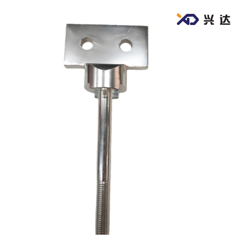
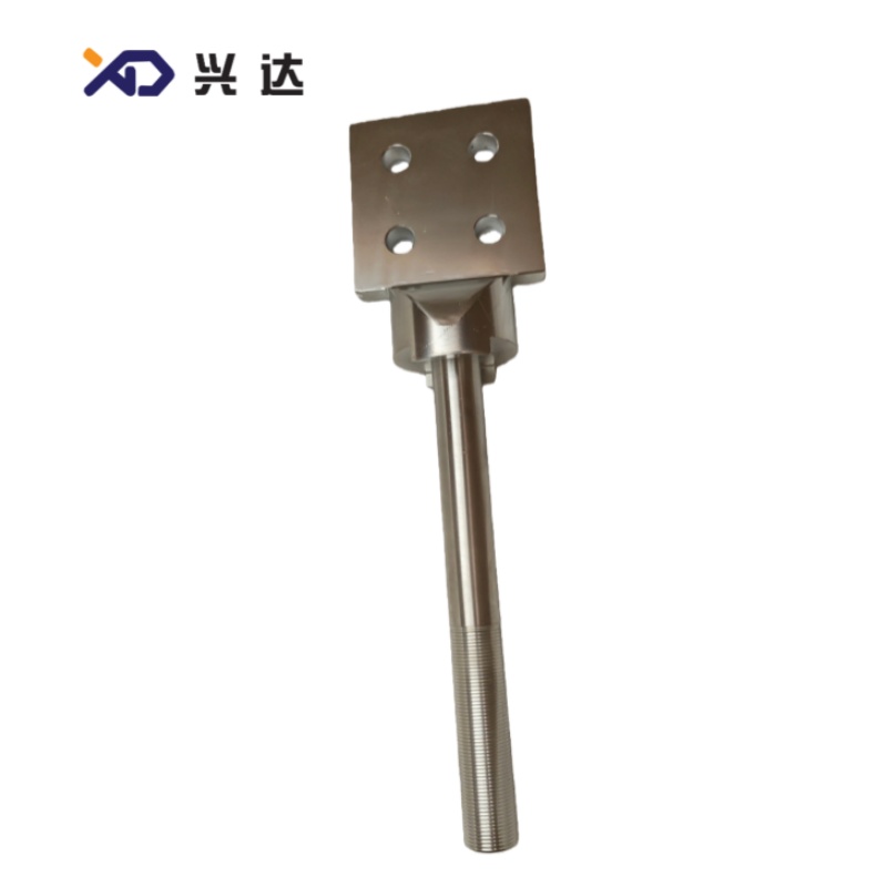
Transformer Bushing Conductor Rod: Technical Guide, Specifications, Materials and Applications A transformer bushing conductor rod is a key conductive component used in transformer bushing assemblies.
Transformer Bushing Conductor Rod: Technical Guide, Specifications, Materials and Applications
A transformer bushing conductor rod is a key conductive component used in transformer bushing assemblies. Its primary function is to provide a continuous electrical path between the internal transformer circuit and the external electrical connection while remaining electrically isolated from the grounded transformer tank.
Transformer bushings are designed to allow energized conductors to pass through grounded transformer structures. Depending on the bushing construction, the conductor may be permanently integrated into the bushing or installed separately as a draw rod, draw lead, or removable conductor.
This guide provides industry-oriented information about transformer bushing conductor rods, including definitions, construction, materials, advantages, technical specifications, applications, selection factors, and common terminology. It is suitable for use as an English SEO article, transformer component category page, technical blog, or product directory page.
1. What Is a Transformer Bushing Conductor Rod?
A transformer bushing conductor rod is a conductive metal rod or conductive assembly installed inside a transformer bushing to carry electrical current through the transformer tank wall.
The basic electrical path can be represented as:
Transformer winding → internal connection → bushing conductor rod → external terminal → power system
The conductor rod is normally surrounded by an insulating structure. Depending on the bushing type, this insulation may consist of porcelain, epoxy, resin-impregnated materials, oil, composite materials, or other engineered insulation systems.
A transformer bushing itself provides an insulated passage for an energized conductor through a grounded transformer tank. The conductor can be built into the bushing or supplied as a separate conductor that is drawn through the bushing.
The conductor rod therefore has two important functions:
1. Electrical function: transmit the required continuous and fault current.
2. Mechanical function: maintain a secure and stable connection between internal and external electrical components.
2. Main Functions of a Bushing Conductor Rod
The transformer bushing conductor rod performs several important functions within a transformer system.
Electrical Current Transmission
The conductor provides a low-resistance path for transformer operating current.
Internal-to-External Connection
It connects the transformer winding or internal lead to an external terminal or bus connection.
Mechanical Connection
The conductor may also provide mechanical support for terminals and internal electrical connections.
Short-Circuit Withstand
During transformer faults, the conductor can experience very high thermal and electromagnetic stresses. Its dimensions, material, and connection structure therefore need to be appropriate for the bushing's short-circuit requirements.
Thermal Performance
Electrical resistance produces heat during operation. Proper conductor sizing helps control losses and temperature rise.
3. Transformer Bushing Conductor Rod Materials
The most common conductor materials are copper and aluminum.
The choice depends on current rating, electrical conductivity, conductor dimensions, mechanical requirements, weight, terminal design, and overall bushing construction.
Copper Conductor Rod
Copper is widely used because of its high electrical conductivity and good thermal and mechanical characteristics.
Typical advantages include:
· High electrical conductivity
· Low electrical resistance
· High current-carrying capability
· Good thermal conductivity
· Good mechanical strength
· Compact conductor dimensions
· Reliable electrical connections
A technical guide for transformer bushings describes solid rod conductors made from electrolytic copper and identifies solid copper rods as an option for maximum current capacity in the applicable bushing design.
Aluminum Conductor Rod
Aluminum is also used for transformer bushing conductors and terminals.
Its main advantages include:
· Low weight
· Good electrical conductivity
· Good thermal conductivity
· Lower material density
· Suitability for larger conductor sections
· Reduced mechanical weight
Some transformer bushing designs use aluminum or copper for external terminals and aluminum or copper for current-carrying internal components, depending on the specific design.
4. Copper vs. Aluminum Conductor Rod
Feature | Copper Conductor Rod | Aluminum Conductor Rod |
Electrical conductivity | Very high | High |
Density | High | Low |
Weight | Higher | Lower |
Thermal conductivity | Excellent | Good |
Compact design | Excellent | Requires larger cross-section |
Mechanical properties | Generally strong | Alloy dependent |
Current-carrying capability | Excellent | Very good when correctly sized |
Weight-sensitive applications | Less favorable | Favorable |
Common applications | High-current compact designs | Lightweight conductor systems |
Connection considerations | Relatively straightforward | Requires careful joint design |
The choice between copper and aluminum should be based on the complete bushing design rather than material conductivity alone.
5. Solid Rod Conductor Construction
A solid rod conductor is a rigid cylindrical conductor installed through or inside the bushing.
Solid rod construction is particularly useful where:
· High current is required
· A rigid electrical path is desirable
· Compact dimensions are important
· High mechanical strength is required
· A robust terminal connection is needed
Some high-voltage transformer bushing designs use divided solid copper rods to simplify assembly. Technical documentation for one bushing design specifically describes an electrolytic copper solid rod divided into sections for easier assembly.
A solid rod may contain:
· Main conductive body
· Threaded section
· Terminal connection
· Mounting section
· Connection holes
· Joint section
· Contact surfaces
6. Draw Rod and Draw Lead Designs
Not every transformer bushing uses a permanently fixed solid conductor.
A draw rod bushing is designed to allow a conductor or lead to be drawn through the central opening of the bushing and connected during transformer assembly.
A draw lead is generally a flexible conductive connection that can provide greater installation flexibility.
Transformer bushing designs can therefore include:
· Fixed conductor
· Solid rod conductor
· Removable conductor
· Draw rod
· Draw lead
· Flexible lead
The selection depends on transformer construction, rated current, installation method, and bushing design.
7. Typical Transformer Bushing Conductor Rod Specifications
The following table provides a practical specification structure for SEO and technical catalog content.
Parameter | Typical Specification |
Product name | Transformer Bushing Conductor Rod |
Conductor type | Solid rod / Draw rod / Fixed conductor |
Material | Copper / Aluminum |
Conductor diameter | Customized according to design |
Conductor length | Customized |
Cross-sectional area | Application dependent |
Rated current | According to bushing rating |
Rated voltage | Determined by complete bushing |
Terminal type | Threaded / Bolted / Stud / Plate |
Connection method | Threaded / Bolted / Brazed |
Surface treatment | Bare / Tin-plated / Silver-plated |
Short-time current | According to design |
Mechanical strength | Application dependent |
Temperature rise | According to applicable bushing requirements |
Insulation compatibility | According to bushing insulation system |
Installation | Transformer bushing assembly |
Customization | Available according to technical drawing |
8. Conductor Rod Diameter
Conductor diameter is one of the most important mechanical and electrical dimensions.
For a round solid conductor, the approximate cross-sectional area can be calculated as:
A = πd² / 4
Where:
· A = conductor cross-sectional area
· d = conductor diameter
Increasing conductor diameter increases the available conductive area and can reduce electrical resistance.
However, conductor diameter should not be selected based only on current.
The design must also consider:
· Insulation clearance
· Bushing internal diameter
· Terminal dimensions
· Temperature rise
· Mechanical strength
· Short-circuit forces
· Electric-field distribution
· Transformer installation space
For this reason, there is no single universal diameter for all transformer bushing conductor rods.
9. Rated Current
Rated current is a fundamental specification for a transformer bushing conductor.
The conductor must be capable of carrying the required continuous current while maintaining acceptable temperature rise.
IEC 60137 is the major international standard for insulated bushings for alternating voltages above 1,000 V and covers bushings used with electrical apparatus, including transformers. It includes characteristics and testing requirements for applicable bushing designs.
The conductor design must therefore be coordinated with the complete bushing rating.
Typical considerations include:
· Transformer rated current
· Bushing rated current
· Conductor material
· Conductor cross-section
· Cooling conditions
· Ambient temperature
· Transformer oil temperature
· Terminal resistance
· Short-circuit current
10. Electrical Resistance of a Conductor Rod
The approximate resistance of a conductor can be expressed as:
R = ρL/A
Where:
· R = resistance
· ρ = material resistivity
· L = conductor length
· A = cross-sectional area
Lower resistance generally means lower electrical losses.
Power loss can be approximated by:
P = I²R
This relationship is particularly important for high-current transformer bushings because even relatively small increases in resistance can produce significant additional heat.
For this reason, conductor material, diameter, length, contact resistance, and terminal design should be evaluated together.
11. Thermal Performance
Transformer bushing conductor rods operate under continuous electrical load.
As current flows through the conductor, resistive losses produce heat.
The resulting temperature depends on:
· Current
· Conductor resistance
· Conductor dimensions
· Material
· Ambient temperature
· Transformer oil temperature
· Heat-transfer conditions
· Terminal design
· Bushing construction
An undersized conductor can cause excessive temperature rise.
An improperly tightened terminal can also create localized heating because the contact resistance may become higher than the resistance of the conductor itself.
IEC 60137 includes temperature-rise testing requirements for applicable bushing constructions.
12. Short-Circuit Performance
A transformer bushing conductor may experience very high current during a transformer fault.
Short-circuit conditions create two major stresses:
Thermal stress
High current generates rapid heating.
Electromagnetic stress
Large current can produce significant mechanical forces between conductors and conductive components.
The conductor rod therefore requires adequate:
· Cross-sectional area
· Mechanical strength
· Joint strength
· Terminal strength
· Support
· Short-time current capability
Short-circuit performance is evaluated as part of the overall bushing design.
13. Transformer Bushing Conductor Rod Advantages
A properly designed conductor rod provides several important benefits.
High electrical conductivity
Copper or aluminum conductors provide an efficient electrical path.
Low electrical losses
Appropriate conductor dimensions can help reduce resistive losses.
Reliable current transmission
The conductor provides a continuous connection between transformer and external circuit.
High mechanical stability
Rigid rod designs can provide strong mechanical support.
Good thermal performance
Correct conductor sizing helps control temperature rise.
Customizable construction
Diameter, length, terminal structure, material, and connection method can be adapted to specific transformer designs.
Long service potential
A properly designed and maintained conductor assembly can provide reliable operation over a long transformer service life.
14. Transformer Bushing Conductor Rod Applications
Transformer bushing conductor rods are used in many types of electrical equipment.
Common applications include:
· Power transformers
· Distribution transformers
· Oil-immersed transformers
· Step-up transformers
· Step-down transformers
· Generator transformers
· Industrial transformers
· Furnace transformers
· Rectifier transformers
· Traction transformers
· Reactors
· High-current electrical equipment
They can be installed on:
· High-voltage transformer sides
· Medium-voltage transformer sides
· Low-voltage transformer sides
· Neutral connections
· Special transformer terminals
The specific conductor arrangement depends on the transformer design.
15. Low-Voltage Transformer Bushing Conductors
Low-voltage transformer bushings can require very high current ratings.
Although the voltage level is lower, transformer secondary current can be substantial.
Therefore, low-voltage conductor rods often emphasize:
· Large cross-sectional area
· Low resistance
· High current capacity
· Efficient heat dissipation
· Strong terminal connections
· Mechanical stability
Some low-voltage solid or bulk bushing designs use central copper or aluminum conductors surrounded by porcelain, epoxy, or thermoplastic insulation. Published technical product information shows that such bushing designs can cover a wide range of current ratings depending on the specific construction.
16. Medium-Voltage Transformer Bushing Conductors
Medium-voltage bushing conductors must balance current capacity with insulation requirements.
Important parameters include:
Parameter | Importance |
Rated voltage | Determines insulation requirements |
Rated current | Determines conductor requirements |
Rod diameter | Affects current capacity and geometry |
Conductor material | Affects resistance and weight |
Insulation | Provides electrical isolation |
Clearance | Controls electrical separation |
Terminal design | Provides external connection |
Short-circuit rating | Determines fault withstand |
17. High-Voltage Transformer Bushing Conductors
High-voltage bushings require more sophisticated insulation and electric-field control.
IEC 60137:2017 covers insulated bushings for AC systems with equipment voltages above 1,000 V and includes special requirements for transformer and reactor bushings.
High-voltage bushing designs can include:
· Central conductor
· Condenser body
· Grading layers
· Shielding electrodes
· Insulating body
· External insulator
· Transformer-side connection
· External terminal
The conductor rod is therefore only one part of the complete high-voltage insulation system.
18. Transformer Bushing Conductor Rod and Insulation
The conductor rod must remain electrically isolated from the grounded transformer tank.
Depending on the bushing construction, surrounding insulation may include:
· Porcelain
· Epoxy
· Resin
· Resin-impregnated paper
· Resin-impregnated synthetic materials
· Transformer oil
· Composite insulation
Solid or bulk bushings commonly use a central conductor surrounded by an insulating material, while capacitance-graded bushings use conductive grading layers within the insulation to control the electric field.
19. Conductor Rod and Electric Field Control
At high voltage, conductor geometry becomes increasingly important.
Sharp edges or abrupt changes in conductor geometry can create areas of increased electric-field stress.
Therefore, high-voltage conductor designs may use:
· Rounded edges
· Smooth transitions
· Shielding
· Grading electrodes
· Controlled conductor geometry
The conductor must be positioned correctly relative to the insulation and grading system.
A transformer bushing conductor should therefore be considered part of the complete electrical-field design.
20. Terminal Design
The conductor rod normally connects to one or more terminals.
Common terminal configurations include:
· Threaded stud
· Bolted terminal
· Flat terminal
· Cable connection
· Terminal plate
· Lug connection
· Custom connector
The terminal material may be:
· Copper
· Aluminum
· Copper alloy
· Plated conductive material
Surface treatment can include:
· Tin plating
· Silver plating
· Other protective finishes
The correct terminal design depends on current rating, connection type, environmental conditions, and the materials being joined.
21. Contact Resistance
Contact resistance is an important consideration in transformer bushing conductor assemblies.
Even when the conductor itself has very low resistance, the connection between the conductor and terminal can introduce additional resistance.
Potential causes of increased contact resistance include:
· Loose connections
· Oxidized surfaces
· Insufficient contact area
· Incorrect tightening
· Contamination
· Improper material combination
· Damaged contact surfaces
Because power loss follows the I²R relationship, contact resistance becomes particularly important in high-current transformer applications.
22. Surface Treatment
Conductor rods may be supplied with different surface finishes depending on the application.
Possible surface conditions include:
· Bare copper
· Bare aluminum
· Tin-plated copper
· Silver-plated copper
· Other engineered surface treatments
Surface treatment may be used to improve:
· Contact characteristics
· Corrosion resistance
· Material compatibility
· Surface stability
· Long-term connection reliability
The appropriate finish should be determined according to the electrical connection and environmental requirements.
23. Manufacturing Process
A typical transformer bushing conductor rod manufacturing process may include:
Step 1 — Material preparation
Copper or aluminum raw material is selected according to the engineering specification.
Step 2 — Cutting
The conductor is cut to the specified length.
Step 3 — Machining
Threads, holes, grooves, shoulders, and terminal sections are machined as required.
Step 4 — Forming
Some designs may require forming or other mechanical processes.
Step 5 — Surface treatment
The conductor may be cleaned, polished, plated, or otherwise finished.
Step 6 — Inspection
Dimensions, surface quality, conductivity, and mechanical features are inspected.
Step 7 — Final cleaning
The finished conductor is cleaned to remove particles and machining residue.
Step 8 — Packaging
Protective packaging is used to prevent damage and contamination.
24. Quality Control
Quality control for transformer bushing conductor rods may include:
Inspection Item | Purpose |
Material verification | Confirm specified conductor material |
Diameter measurement | Verify conductor size |
Length measurement | Verify installation dimensions |
Thread inspection | Confirm terminal compatibility |
Hole inspection | Confirm connection dimensions |
Straightness inspection | Ensure proper assembly |
Surface inspection | Detect scratches and defects |
Conductivity testing | Verify electrical performance |
Resistance testing | Check conductive path |
Visual inspection | Detect manufacturing defects |
For high-voltage transformer components, cleanliness and dimensional consistency are especially important.
25. Installation Considerations
The installation procedure depends on the specific transformer bushing.
General considerations include:
1. Confirm the correct conductor specification.
2. Check conductor dimensions.
3. Inspect the rod for mechanical damage.
4. Clean the contact surfaces.
5. Confirm correct installation orientation.
6. Install according to the engineering drawing.
7. Tighten fasteners to the specified torque.
8. Verify alignment.
9. Check clearances.
10. Complete final inspection.
The conductor should not be forced into the bushing if the dimensions or alignment appear incorrect.
26. Maintenance and Inspection
A transformer bushing conductor rod is generally inspected as part of the complete bushing and transformer maintenance program.
Potential inspection methods include:
· Visual inspection
· Thermal imaging
· Electrical resistance checks
· Connection inspection
· Insulation testing
· Partial discharge testing where applicable
Abnormal heating around an external bushing connection can indicate:
· Loose connection
· High contact resistance
· Overloading
· Corrosion
· Damaged terminal
· Incorrect connection
27. Common Transformer Bushing Conductor Rod Problems
Overheating
Possible causes include excessive current, undersized conductor, high contact resistance, or poor cooling.
Loose Connection
A loose connection can increase contact resistance and cause localized heating.
Corrosion
Environmental exposure and incompatible materials can contribute to corrosion.
Mechanical Damage
Improper installation or excessive external loading can damage the conductor.
Thread Damage
Cross-threading or excessive tightening can damage threaded conductor sections.
Surface Contamination
Dirt, moisture, or metal particles can affect electrical and mechanical performance.
28. Transformer Bushing Conductor Rod Selection Guide
When selecting a conductor rod, consider the following factors:
Selection Factor | Key Question |
Transformer rating | What is the transformer power rating? |
Voltage | What is the required voltage class? |
Current | What is the continuous operating current? |
Material | Copper or aluminum? |
Diameter | What conductor size is required? |
Length | What installation length is required? |
Terminal | What terminal configuration is required? |
Connection | Threaded, bolted, brazed, or other? |
Short circuit | What fault current must be withstand? |
Insulation | What bushing insulation system is used? |
Environment | Indoor, outdoor, oil-immersed, etc.? |
Standard | Which technical standard applies? |
Drawing | What dimensional tolerances are required? |
29. Transformer Bushing Conductor Rod vs. Draw Lead
Feature | Conductor Rod | Draw Lead |
Construction | Rigid | Flexible |
Mechanical rigidity | High | Lower |
Installation flexibility | Moderate | High |
Current capacity | Depends on conductor size | Depends on cable/lead size |
Connection | Rod/terminal based | Flexible connection |
Space | Defined geometry | More adaptable |
Typical use | High-current or rigid connection | Flexible internal connection |
Some bushing designs specifically use solid rods for higher current capacity and flexible leads when easier assembly is more important and the required current is lower.
30. Typical Technical Specification Table
The following format can be used directly on a product or category page.
Item | Specification |
Product | Transformer Bushing Conductor Rod |
Application | Transformer Bushing |
Conductor Type | Solid Rod / Draw Rod |
Material | Electrolytic Copper / Aluminum |
Rod Diameter | Customized |
Rod Length | Customized |
Cross-Section | Customized |
Rated Current | According to Bushing Design |
Voltage Class | According to Complete Bushing |
Terminal Type | Stud / Thread / Plate / Lug |
Connection | Bolted / Threaded / Brazed |
Surface Finish | Bare / Tin-Plated / Silver-Plated |
Short-Time Current | Application Specific |
Mechanical Strength | Application Specific |
Temperature Rise | According to Applicable Requirements |
Insulation Compatibility | Transformer Bushing Insulation |
Manufacturing Tolerance | According to Engineering Drawing |
Application | Power / Distribution Transformer |
Customization | Available |
31. Key Advantages for Product Pages
A transformer bushing conductor rod can be described using the following technical selling points:
· High electrical conductivity
· Low electrical resistance
· Reliable current transmission
· High current-carrying capability
· Excellent dimensional accuracy
· Strong mechanical construction
· Reliable terminal connection
· Good thermal performance
· Suitable for transformer bushing applications
· Copper and aluminum material options
· Solid rod and draw rod configurations
· Customized dimensions
· Suitable for high-current applications
· Compatible with different bushing structures
· Designed according to application requirements
32. SEO Keyword List
Primary Keywords
· transformer bushing conductor rod
· transformer bushing conductor
· bushing conductor rod
· transformer conductor rod
· transformer bushing rod
Secondary Keywords
· copper transformer bushing conductor
· aluminum transformer bushing conductor
· solid copper conductor rod
· transformer bushing terminal
· transformer bushing conductor material
· transformer bushing conductor diameter
· transformer bushing rated current
· transformer bushing conductor specification
· high voltage bushing conductor
· power transformer bushing conductor
Long-Tail Keywords
· transformer bushing conductor rod specifications
· copper conductor rod for transformer bushing
· aluminum conductor rod for transformer bushing
· solid rod conductor for transformer
· transformer bushing conductor dimensions
· transformer bushing conductor material
· transformer bushing conductor current rating
· high current transformer bushing conductor
· transformer bushing conductor technical data
· transformer bushing conductor rod application
33. SEO-Friendly Product Description
Transformer Bushing Conductor Rod is a precision conductive component designed to provide a reliable electrical connection through transformer bushing assemblies. Manufactured from high-conductivity copper or aluminum, the conductor rod can be configured as a solid rod, draw rod, fixed conductor, or customized conductive assembly.
The transformer bushing conductor rod is designed according to required current rating, conductor diameter, cross-sectional area, terminal configuration, mechanical strength, thermal performance, and bushing insulation structure. It is widely applicable to power transformers, distribution transformers, oil-immersed transformers, reactors, and other electrical equipment.
Customized conductor rod dimensions, connection structures, terminal configurations, and surface treatments can be specified according to engineering drawings and transformer bushing requirements.
34. SEO-Friendly Meta Title
Transformer Bushing Conductor Rod | Copper & Aluminum Specifications
Meta Description
Learn about transformer bushing conductor rods, including copper and aluminum materials, solid rod construction, rated current, conductor dimensions, terminals, applications, advantages, and technical specifications.
35. Conclusion
The transformer bushing conductor rod is a fundamental current-carrying component in transformer bushing systems. Its purpose is to provide a reliable electrical path between the transformer internal circuit and the external power connection while remaining properly insulated from the grounded transformer tank.
Copper and aluminum are the primary conductor materials. Copper offers high conductivity and compact dimensions, while aluminum provides a lightweight alternative for applications where a larger conductor cross-section can be accommodated.
The most important conductor rod specifications include:
· Material
· Diameter
· Length
· Cross-sectional area
· Rated current
· Terminal design
· Connection method
· Surface treatment
· Mechanical strength
· Short-circuit capability
· Thermal performance
· Insulation compatibility
For high-voltage applications, the conductor must also be integrated correctly with the bushing's electric-field and insulation system.
IEC 60137:2017 is an important international reference for insulated bushings used with AC electrical equipment above 1,000 V, including transformer and reactor bushings.
A correctly designed transformer bushing conductor rod helps provide low electrical resistance, stable current transmission, controlled temperature rise, reliable mechanical connections, and long-term transformer bushing performance. It should therefore be selected as part of the complete bushing system rather than as an isolated metal component.
Categories
Contact Us
Contact: Tianjin Delda Trading Co., Ltd
WhatsApp: +86 13662056855
Tel:
E-mail: solomon20210701@tjxddq.com
Add: Unit‑101, Workshop 3, Bozhong Automobile Industrial Park, No.5 Xianghui Road, Intersection of Xianghui Road and Gaoying Road, Beizhakou Town, Jinnan District, Tianjin, China