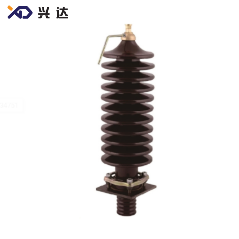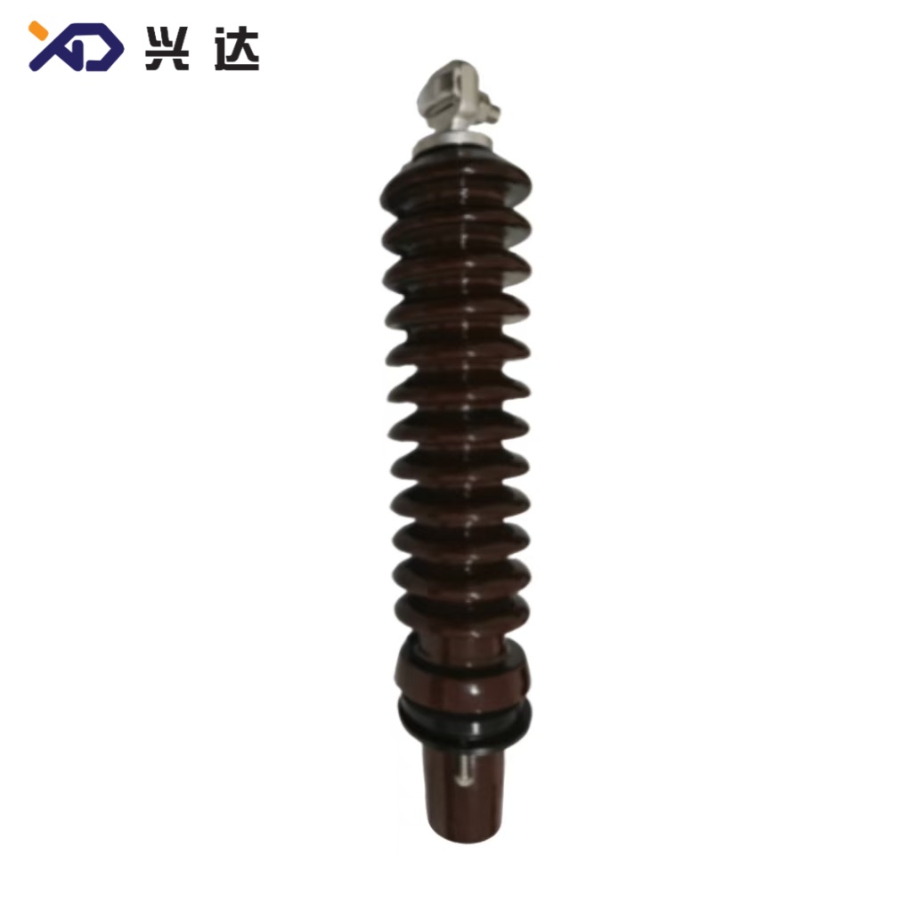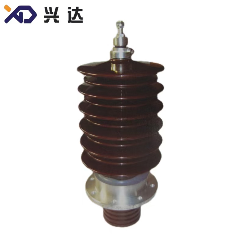
Renewable energy installations including on‑shore wind farms, offshore wind turbine stations and large‑scale photovoltaic power plants are rapidly expanding across global power grids. As new‑energy power generation capacity keeps growing, auxiliary electrical components must adapt to unique operational environments, frequent load fluctuations and strict safety requirements for power transformation equipment. A flange‑type bushing for wind power and photovoltaic systems serves as a critical insulating and conducting interface for new‑energy transformers.
This category of flange‑mounted bushing creates a reliable passage for live conductors to penetrate the grounded transformer tank. It combines high‑voltage insulation performance with solid mechanical flange connection structure. Unlike standard distribution transformer bushings, wind‑PV dedicated flange‑type bushings are engineered to cope with variable output current from wind turbines and solar arrays, wide temperature swings, outdoor ultraviolet exposure and occasional vibration caused by wind turbine operation. These components are widely fitted on box‑type transformers, step‑up transformers for wind power and photovoltaic power station transformers.
In new‑energy power projects, bushing failure is one of the leading triggers for transformer outages. Poor insulation performance, insufficient mechanical strength or inadequate creepage distance will cause partial discharge, flash‑over and even catastrophic equipment damage. Therefore, proper selection of flange‑type bushings matching wind‑PV operating conditions is fundamental to maximize uptime for renewable power facilities.
A wind‑photovoltaic flange‑type bushing is a special‑purpose high‑voltage bushing adopting flange mounting structure, designed for transformers deployed in wind farms and photovoltaic power stations. The integrated flange base enables fast, stable sealing installation on transformer tank openings. The internal conductor transfers rated current, while external porcelain or composite housing provides sufficient electrical insulation against phase‑to‑ground voltage.
Different from conventional general‑purpose transformer bushings, wind‑PV flange‑type bushings take multiple new‑energy working conditions into account during design: frequent load variation, continuous vibration, broad ambient temperature range, outdoor pollution and humidity. The product family covers typical voltage class 40.5 kV and common current rating 100 A, with multiple dimensional variants to satisfy different transformer tank layout demands. Two mainstream configurations are widely adopted in the industry, differing mainly in creepage distance, arcing distance and overall structural dimensions.
Robust Flange Mounting StructureThe built‑in flange base offers large contact area with transformer tank. Uniform bolt layout ensures reliable mechanical fixation and stable compression for rubber sealing gaskets. It effectively prevents oil leakage from transformer tank openings under vibration scenarios such as wind turbine running. Installation and field replacement procedures are straightforward for on‑site maintenance teams.
Optimized Insulation Performance for Outdoor Renewable ScenariosExtended creepage distance and arcing distance are implemented to resist contamination, dew and salt fog. The housing material delivers excellent anti‑tracking property. It can sustain specified power‑frequency withstand voltage and lightning impulse voltage, lowering flash‑over risk under harsh outdoor atmospheric conditions.
Strong Mechanical Load ResistanceQualified wind‑PV flange‑type bushings pass bending load test. Good mechanical strength tolerates external mechanical stress, transportation shock and long‑term minor vibration from wind‑turbine equipment, avoiding internal structural damage.
Stable Thermal Performance under Variable‑load ConditionsWind power and photovoltaic output fluctuates with wind speed and solar irradiance, leading to frequent current changes inside transformers. The internal conductive structure of this bushing is optimized for cyclic load, maintaining reasonable temperature rise under continuous operation and avoiding overheating risks caused by unstable power generation output.
Flexible Dimensional Customization CompatibilityMultiple standard dimension series are available for mainstream new‑energy transformer models. Non‑standard dimensions can be customized to match special tank opening sizes, installation height and space constraints of wind‑power step‑up transformers. Different sealing rubber material options such as nitrile rubber and fluorine rubber can be selected according to ambient environment requirements.
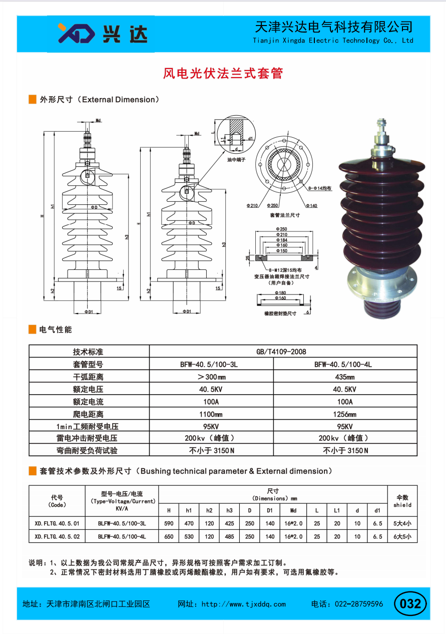
General industry‑wide typical parameters for 40.5 kV wind‑photovoltaic flange‑type bushings
| Item | Specification Variant 1 | Specification Variant 2 |
|---|---|---|
| Rated Voltage | 40.5 kV | 40.5 kV |
| Rated Current | 100 A | 100 A |
| Minimum Arcing Distance | >300 mm | 435 mm |
| Creepage Distance | 1100 mm | 1256 mm |
| 1‑min Power‑frequency Withstand Voltage | 95 kV | 95 kV |
| Lightning Impulse Withstand Voltage (peak value) | 200 kV | 200 kV |
| Minimum Bending Test Load | 3150 N | 3150 N |
| Shield Configuration | 5 large 4 small | 6 large 5 small |
All dimension units: millimeter (mm)
| Code | Model‑Voltage/Current | H | h1 | h2 | h3 | D | D1 | Md | L | L1 | d | d1 |
|---|---|---|---|---|---|---|---|---|---|---|---|---|
| XD.FLTG.40.5.01 | BLFW‑40.5/100‑3L | 590 | 470 | 120 | 425 | 250 | 140 | 16*2.0 | 25 | 20 | 10 | 6.5 |
| XD.FLTG.40.5.02 | BLFW‑40.5/100‑4L | 650 | 530 | 120 | 485 | 250 | 140 | 16*2.0 | 25 | 20 | 10 | 6.5 |
Wind Farm Step‑up TransformersOn‑shore and offshore wind turbine box‑type step‑up transformers are the largest application field. The flange‑type bushing connects transformer internal windings to external circuits, resisting vibration generated by wind‑turbine rotation.
Photovoltaic Power Station TransformersCentralized and distributed solar PV power plants require transformers to boost generated voltage. Flange‑type bushings handle variable power output from photovoltaic arrays and adapt to open‑air site environment.
New‑Energy Micro‑grid Power EquipmentHybrid wind‑solar micro‑grid projects also widely deploy this type of bushing on power transformers for energy‑storage supporting facilities.
When specifying flange‑type bushings for wind power and photovoltaic projects, engineers should evaluate multiple critical factors:
Rated voltage and rated current must match transformer design parameters.
Arcing distance and creepage distance shall be chosen based on site pollution grade and altitude. For high‑altitude locations above 1000 m, insulation parameters need corresponding altitude correction.
Overall installation height, flange dimension and tank‑opening size must fit transformer mechanical layout.
Confirm mechanical bending load index for locations with persistent vibration.
Select sealing gasket material according to site temperature, chemical corrosion and weather conditions: nitrile rubber for general conditions, fluorine rubber for harsh corrosive environment.
Check shield configuration requirements according to partial‑discharge control demands of the whole transformer.
Check visual appearance for housing cracks, flange deformation and thread damage before installation.
Place rubber sealing gasket evenly between bushing flange and transformer tank surface; tighten flange bolts cross‑wise with proper torque to prevent oil leakage. Avoid over‑torque which may crack porcelain housing.
Ensure sufficient clearance to surrounding metal structures after mounting, to satisfy insulation safety distance.
During routine maintenance, inspect surface contamination level, seal leakage condition and connection terminal temperature. Clean housing surface when excessive pollution accumulates.
Avoid heavy impact to the bushing during transformer transportation and on‑site hoisting.
Oil leakage at flange joint: Mostly caused by uneven bolt torque, aging or mis‑placed sealing gasket. Standardize bolt tightening sequence and select appropriate gasket material.
Surface flash‑over: Usually triggered by insufficient creepage distance or heavy surface contamination. Select proper creepage class matching site pollution level and arrange periodical cleaning.
Internal over‑heating: Mainly comes from poor contact of inner conductive parts. Follow technical requirement for terminal connection torque during assembly.
Mechanical damage: Resulting from external impact or long‑time excessive vibration. Take protective measures in transportation and choose products meeting required bending‑load standard.
Flange‑type bushing for wind power and photovoltaic systems is a specialized insulating component tailored for renewable energy transformers. Its unique flange mounting architecture, enhanced insulation indexes and vibration‑resistant mechanical performance make it well‑suited for wind farms and solar PV stations. Correct parameter selection, standardized installation and regular maintenance are essential to secure long‑term reliable operation for new‑energy power transformation equipment. As global renewable energy capacity keeps expanding, qualified wind‑PV flange‑type bushings will continue to play an irreplaceable role in power‑grid‑connected wind and solar projects.
Contact: Tianjin Delda Trading Co., Ltd
WhatsApp: +86 13662056855
Tel:
E-mail: solomon20210701@tjxddq.com
Add: 55-302 Xiaoyuan New Village, Tianjin Economic and Technological Development Zone, China