Gas relay
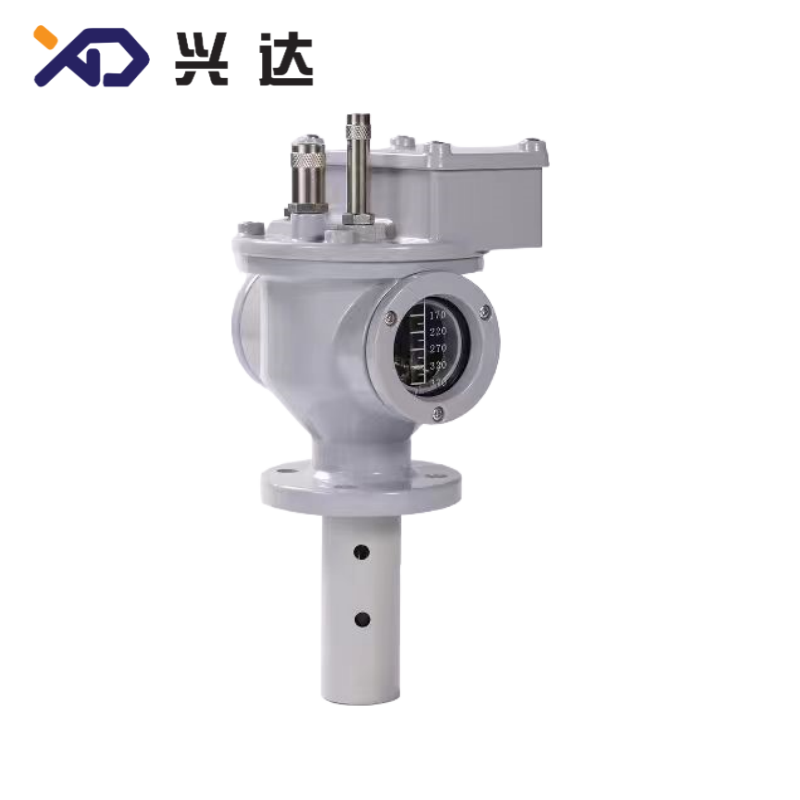
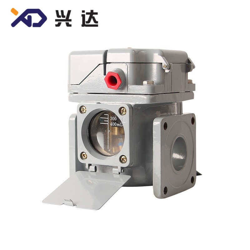
Gas Relay for Oil Immersed Power Transformers
Gas Relay (Buchholz Relay) SEO Complete Package
1. What Is a Gas Relay?
Gas relay protection is regarded as the primary internal fault protection for oil-filled transformers. It complements differential protection, over-current protection and temperature protection to build a complete transformer safety protection system. It cannot be applied for dry-type transformers without insulating oil and conservator.
2. Operating Principle of Gas Relay
When severe short-circuit or heavy arcing faults arise, massive gas is generated in a short time, creating strong oil flow shock toward the conservator. The high-speed oil flow strikes the lower baffle, pushing the baffle to rotate and close the trip contact. This signal commands the circuit breaker to cut off power supply immediately to isolate the faulty transformer.
3. Two-Stage Protection Function
3.1 Gas Alarm Protection (First Stage)
- Slow aging of insulating materials with minor thermal decomposition
- Tiny air leakage; air entering the transformer tank during maintenance
- Weak partial discharge or low-energy local overheating
- Slow oil leakage leading to gradual oil level reduction
3.2 Oil Surge Trip Protection (Second Stage)
- Phase-to-phase short circuit of transformer windings
- Turn-to-turn winding short circuit
- Core insulation breakdown, heavy internal arcing
- Large-scale internal metal short-circuit faults
Once the trip contact closes, the transformer will be disconnected from the grid to avoid tank rupture, oil ignition or permanent scrap of equipment.
4. Main Classifications of Gas Relays
4.1 By Internal Sensing Structure
- Float-baffle type gas relay: The most common standard type, equipped with upper float for gas alarm and lower baffle for surge trip. Widely used for medium and large power transformers.
- Single float type gas relay: Simplified structure, mostly applied on small distribution transformers, only supporting gas alarm function without reliable trip protection.
4.2 By Nominal Pipe Diameter
4.3 By Contact Output Type
- Mechanical contact output: Dry contact for simple signal connection, widely adopted in traditional power systems.
- Auxiliary electronic signal output: Compatible with modern intelligent substation monitoring systems.
5. Universal Technical Specification Reference Table
| Parameter Item | Standard Range | Supplementary Notes |
|---|---|---|
| Nominal Connection Diameter | DN25, DN50, DN80 | Match the pipeline between transformer tank and conservator |
| Alarm Setting Gas Volume | 250 ~ 300 cm³ | Adjustable according to project requirements |
| Trip Setting Oil Flow Velocity | 0.6 ~ 1.5 m/s | Standard default setting: 1.0 m/s |
| Contact Rated Voltage | AC 220V / DC 220V | Control circuit universal voltage |
| Contact Rated Current | 1A ~ 5A | Resistive load standard parameter |
| Installation Angle Requirement | Horizontal mounting, tilt tolerance ≤2° | Strict installation gradient standard |
| Operating Ambient Temperature | -30°C ~ +75°C | Adapt to outdoor substation environment |
| Housing Material | Cast Aluminum Alloy | Anti-rust, oil resistant, mechanical impact resistance |
| Compliance Standards | IEC 60255, GB/T 6451 | International transformer protection device standards |
| Medium Compatibility | Mineral insulating transformer oil | Not applicable for synthetic oil without special customization |
6. Comparison: Gas Alarm vs Trip Protection
| Item | Gas Alarm (Upper Float) | Oil Surge Trip (Lower Baffle) |
|---|---|---|
| Trigger Condition | Accumulated gas volume threshold | Transient oil flow velocity threshold |
| Corresponding Fault Severity | Mild, slow developing defects | Severe, sudden internal short-circuit faults |
| System Action | Send warning signal, keep transformer running | Trigger circuit breaker to cut off power immediately |
| Response Speed | Slow, gas accumulates gradually | Instant response within milliseconds |
| Common Failure Causes | Insulation aging, air ingress, small overheating | Winding short circuit, internal arc fault |
| Operation Strategy | Arrange inspection and DGA testing | Forbid re-energizing until complete internal check |
7. Core Advantages of Gas Relay
- Sensitive Detection of Early Internal Transformer FaultsGas relay can identify low-energy faults which voltage and current protection devices cannot detect in early phases, providing early warning for hidden risks.
- Two-Tier Safety MechanismSeparate alarm and trip outputs allow staged risk handling: monitor minor abnormalities while realizing emergency shutdown for dangerous failures.
- Simple and Reliable Mechanical StructureMain models adopt pure mechanical driving structure, less affected by electromagnetic interference, high stability in complex substation electromagnetic environment.
- Low Long-Term Operating CostNo continuous power consumption required during normal operation; minimal routine maintenance workload.
- Convenient Fault AnalysisThe gas collection valve on the relay allows technicians to extract accumulated gas for composition testing, helping judge fault types accurately.
- Wide CompatibilityStandard flange sizes fit most oil immersed distribution transformers, substation transformers and new energy step-up transformers globally.
8. Standard Installation Requirements
- The gas relay must be installed horizontally on the pipeline connecting transformer tank and oil conservator.
- The oil pipeline should maintain a rising gradient of 1% ~ 1.5% toward the conservator, preventing gas from being trapped in front of the relay.
- Install isolation valves on both sides of the relay to allow disassembly without draining large amounts of transformer oil.
- Keep the marking arrow on the relay housing pointing toward the oil conservator to guarantee correct oil flow direction.
Avoid vibration sources nearby; excessive long-term vibration may cause false signal triggering.
9. Global Industry Standards
- IEC 60255: Measuring relays and protection equipment, basic performance requirements for gas relay auxiliary contacts.
- IEC 60076: Power transformer standard, specifies gas relay configuration requirements for oil immersed transformers.
Regional standards such as GB/T 6451, EN standards provide detailed installation and testing specifications.
All qualified gas relays must pass air tightness test, action characteristic calibration and mechanical endurance test before factory delivery.
10. Typical Application Scenarios
- Oil immersed distribution transformers for urban and rural power grids
- Medium & high voltage main transformers in power substations
- Step-up transformers for wind farms and photovoltaic power plants
- Large industrial transformers for mining, chemical and steel plants
- Oil immersed traction transformers for railway power supply
Oil immersed shunt reactors in transmission systems
11. Operation & Maintenance Guidelines
- Monthly visual inspection: Check for oil leakage at flange connections, observe whether gas accumulates inside the relay sight glass.
- Annual calibration: Verify alarm gas volume and trip oil flow speed setting values.
- Regularly release accumulated gas via the gas sampling cock; record gas volume and perform gas analysis if necessary.
- After transformer maintenance, exhaust all trapped air inside the gas relay to avoid false alarm signals.
- Check contact wiring terminals regularly to prevent loose connections leading to signal failure.
12. Frequently Asked Questions
Q1: Can gas relay be used on dry-type transformers?
Q2: Why does the gas relay send false alarms?
Q3: Does gas relay replace transformer differential protection?
Q4: Is it allowed to put the transformer into operation immediately after trip action?
Categories
Contact Us
Contact: Tianjin Delda Trading Co., Ltd
WhatsApp: +86 13662056855
Tel:
E-mail: solomon20210701@tjxddq.com
Add: Unit‑101, Workshop 3, Bozhong Automobile Industrial Park, No.5 Xianghui Road, Intersection of Xianghui Road and Gaoying Road, Beizhakou Town, Jinnan District, Tianjin, China