Tap changer
Tap Changer – Complete Technical Guide for Oil‑Immersed Distribution & Power Transformers
Tap Changer – Complete Technical Guide for Oil‑Immersed Distribution & Power Transformers
What is a Tap Changer
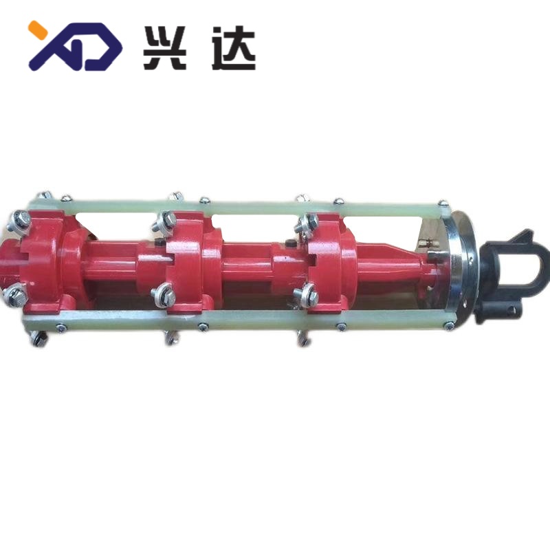
A tap changer is a core regulating switch device fitted on power and distribution transformers, designed to adjust transformer winding turns‑ratio for stabilizing output voltage under fluctuating grid supply conditions. By selecting different tap positions on high‑voltage winding taps, it compensates voltage deviations caused by long‑distance line drop, seasonal load variation and grid source drift.
Tap changers are divided into two major technical categories: de‑energized tap changer (DETC / off‑circuit / no‑load tap changer) and on‑load tap changer (OLTC). De‑energized tap changers must be adjusted only after transformer full de‑energization and lock‑out procedures. On‑load tap changers can complete tap‑switching while transformer remains energized and carries operational load current.
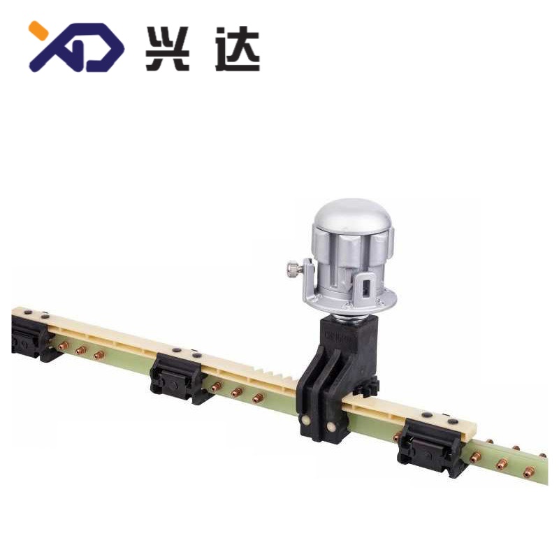
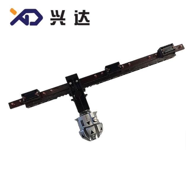
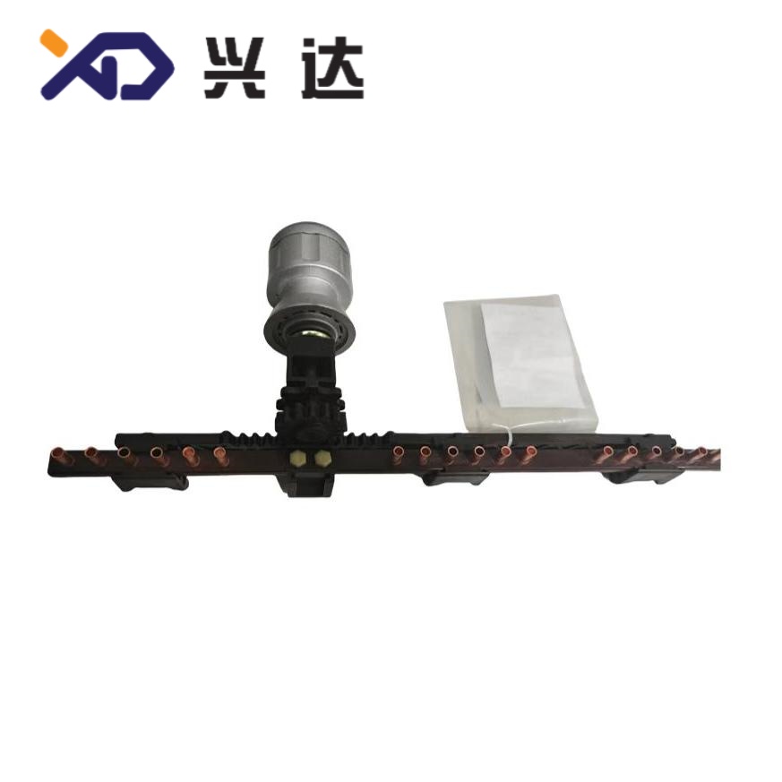
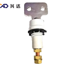
For ANSI single‑phase pole‑mounted distribution transformers, the bar‑form tap changer (linear sliding‑contact structure) is widely adopted, which installs horizontally inside transformer tank with external operating knob for manual tap‑position switching after power‑off. For three‑phase IEC / DIN transformers, rotary disc‑type de‑energized tap changers are mainstream options. All tap‑changer products follow international standard IEC 60214‑1: Performance requirements and test methods for tap‑changers and related IEEE C57 series standards for North‑American transformer projects.
Core Tap‑Changer Classification & Comparison
This table outlines key differences between mainstream tap‑changer families, covering operation rules, typical tap range, application scenarios and general characteristics.
| Item | De‑Energized Tap Changer (DETC / Off‑Circuit) | On‑Load Tap Changer (OLTC) |
|---|---|---|
| Operating condition | Must fully de‑energize transformer before tap adjustment | Tap switching under full energized load condition |
| Operating principle | Static sliding / rotary contact, no arc‑suppression parts | Equipped with transition resistor or reactor to limit circulating current during tap transfer |
| Typical tap range | ±2×2.5 % (5‑position:‑5%,‑2.5%,0,+2.5%,+5%) | ±8 % ~ ±16 %, multiple tap‑step combinations |
| Adjustment frequency | Low: seasonal adjustment, commissioning setting, usually less than 5 times per year | High: automatic frequent regulation, several to dozens of operations daily |
| Mechanical structure | Compact, simple contact assembly; bar‑form or disc‑type structure | Complex assembly: tap selector + diverter switch + motor‑drive unit, independent oil compartment |
| Initial cost | Low‑to‑medium | High, includes motor drive and auxiliary monitoring components |
| Maintenance demand | Minimal, visual inspection and DC resistance test periodically | Heavy maintenance: oil replacement, contact wear inspection, drive‑mechanism check |
| Main application | Distribution transformers, pole‑mount / pad‑mount transformers, ANSI single‑phase transformers | Large‑size power transformers, substation transformers, industrial heavy‑load transformers |
Practical note: Bar‑form tap changer belongs to de‑energized tap‑changer subclass, specially optimized for ANSI single‑phase oil‑immersed transformers, featuring horizontal sliding‑contact layout to fit limited internal tank space.
Main Technical Specification Parameters
When engineers specify tap‑changer components for transformer projects, these critical technical parameters must be fully confirmed in procurement documents.
| Parameter | Explanation |
|---|---|
| Rated insulation voltage | Matches transformer primary winding voltage class |
| Rated through‑current | Long‑term continuous current passing through tap‑changer contacts |
| Tap regulation range | Total voltage adjustment scope relative to nominal voltage |
| Tap‑step increment | Single‑step voltage change value between adjacent tap positions |
| Tap position quantity | Number of selectable winding tap points |
| Compliance standard | International performance & test standard |
| Installation form | Operates fully submerged inside transformer mineral oil |
| Mechanical life (DETC) | Total allowable manual tap‑switch cycles |
Key Performance Advantages of Tap‑Changer Devices
- Grid‑voltage deviation compensationTap‑changer solves the problem of output‑voltage drift caused by transmission‑line voltage drop and load fluctuation. De‑energized types finish coarse voltage correction during commissioning or seasonal grid changes. On‑load tap‑changer maintains stable secondary‑side voltage automatically for continuous‑operation critical‑load sites.
- Compact in‑tank oil‑immersed designMost distribution‑transformer tap changers are completely immersed in mineral transformer oil. Oil provides excellent insulation, heat dissipation and anti‑oxidation protection for contact surfaces, extending component service life. Bar‑form DETC adopts slim horizontal layout to save valuable internal tank volume for ANSI single‑phase transformers.
- Reliable contact conduction performanceHigh‑quality silver‑plated copper contacts guarantee low contact resistance. Stable contact pressure avoids local over‑heating risk under rated through‑current. Good spring‑loaded contact structure resists vibration from transformer transport and short‑circuit electromagnetic force.
- Clear human‑operated interface for DETCDe‑energized tap‑changer extends an operating shaft through transformer tank lid, fitted with external position indicator knob. Operators can read tap‑position marks visually without opening transformer tank. Strict warning labels remind operators to cut power before adjustment to avoid catastrophic arc faults.
- Wide‑range standardized optionsMultiple voltage, current and tap‑position grades cover IEC, DIN, EN and ANSI transformer‑design requirements. Standardized mounting dimensions simplify transformer‑manufacturer assembly work.
Common Mis‑operation Risks & Failure Modes
Improper operation, wrong specification selection or poor assembly will trigger transformer hidden faults. The table summarizes frequent field failure patterns, root causes and general counter‑measures.
| Failure phenomenon | Root‑cause analysis | Recommended counter‑measure |
|---|---|---|
| DETC operated under energized condition | Human‑factor mis‑operation; ignoring lock‑out tag‑out procedure | Strictly implement power cut‑off and grounding before adjusting de‑energized tap‑changer |
| Large DC resistance deviation among tap positions | Contact spring fatigue, contact surface oxidation or carbon deposition | Perform DC winding‑resistance test at acceptance and maintenance cycles; inspect contact pressure |
| Tap‑changer mechanical jamming | Foreign‑object debris entering mechanism; shaft mis‑alignment during assembly | Prevent metal scraps falling into tank during production; do not apply excessive torque on external operating knob |
| OLTC oil carbonization & acetylene gas rise | Arc burning inside diverter‑switch compartment during frequent tap‑switching | Carry out DGA dissolved‑gas‑analysis regularly; replace or filter independent OLTC compartment oil according to operation‑count threshold |
| Position‑indicator mismatch with real internal tap position | Operating‑shaft slipping, mechanical assembly offset | After tap‑changing, verify tap‑position mark and cross‑check DC resistance value |
Critical safety reminder: Never attempt to adjust de‑energized tap‑changer when transformer remains live. Contacts of DETC possess zero arc‑quenching capability; live adjustment will generate powerful internal electric arc, potentially causing transformer explosion and permanent equipment damage.
Tap‑Changer Selection Guidance for Transformer Design & Procurement
Four core dimensions should be checked when selecting tap‑changer for oil‑immersed transformers:
- Determine tap‑changer type according to adjustment frequencyIf tap modification occurs only for commissioning or seasonal grid changes, choose cost‑effective de‑energized tap‑changer (bar‑form for ANSI single‑phase transformers, disc‑form for IEC three‑phase transformers). If frequent real‑time voltage stabilization is required for substations or heavy‑load industrial sites, select on‑load tap‑changer with motor‑drive unit.
- Match electrical parameters strictlyConfirm rated insulation voltage ≥ transformer primary voltage; rated through‑current must meet or exceed maximum transformer winding current. Confirm tap range and tap‑step percentage match transformer winding tap‑winding design.
- Check mechanical‑installation dimensionVerify internal mounting space, operating‑shaft height, knob position and tank‑penetration size. For ANSI single‑phase transformers, bar‑form tap‑changer horizontal dimension must fit tank internal geometry.
- Define applicable standard and operating‑environment conditionsSpecify IEC 60214‑1 or corresponding ANSI standard. For high‑altitude, heavy‑pollution or coastal salt‑spray environments, evaluate insulation clearance and anti‑corrosion requirements for metal components.
Maintenance Best Practices
De‑energized Tap Changer (DETC)
- Maintenance cycle: Every 1‑3 years during transformer routine overhaul.
- Inspection items: Confirm tap‑position indication consistency; measure winding DC resistance for every tap position; check operating‑shaft sealing for potential oil‑leak risk; ensure no mechanical jamming by manual knob rotating under power‑off condition.
On‑Load Tap Changer (OLTC)
- Track total tap‑operation‑count log as primary maintenance trigger reference, not only calendar time.
- Regular DGA dissolved‑gas analysis for OLTC dedicated compartment oil; replace oil once reaching operation‑count limit.
Inspect motor‑drive mechanism, limit switches and transition‑resistor integrity during overhaul.
Conclusion
Tap changer acts as indispensable voltage‑regulating component for oil‑immersed transformers. De‑energized tap‑changer (including bar‑form variant for ANSI single‑phase transformers) delivers simple, economical solution for infrequent voltage correction, widely used in distribution‑grade transformers. On‑load tap‑changer realizes live automatic voltage regulation for critical power‑system equipment.
Correct type selection, strict procurement‑parameter confirmation, standardized installation and periodic maintenance together avoid tap‑changer‑related transformer failures. Designers and manufacturing engineers must distinguish DETC and OLTC application boundaries, and enforce safety procedures to forbid energized adjustment for de‑energized tap changers.
PREVIOUS:Tap changer NEXT:Tap changer
Categories
Contact Us
Contact: Tianjin Delda Trading Co., Ltd
WhatsApp: +86 13662056855
Tel:
E-mail: solomon20210701@tjxddq.com
Add: Unit‑101, Workshop 3, Bozhong Automobile Industrial Park, No.5 Xianghui Road, Intersection of Xianghui Road and Gaoying Road, Beizhakou Town, Jinnan District, Tianjin, China