Transformer brass flag
Transformer Brass Flag Bushing Connector Material Options Surface Treatment and Performance
Transformer Brass Flag Bushing Connector: Complete Technical Guide
Transformer brass flag bushing connector is a critical conductive terminal component mounted on power and distribution transformer bushings, widely used to create reliable bolt‑on connections between transformer internal winding leads and external busbars, power cables or overhead line terminations. Also known as brass flag terminal, bushing flag connector or transformer spade terminal, this hardware is engineered for low‑medium voltage transformer applications, complying with ANSI, DIN, EN and IEC industry standards for global power‑system deployment.
Unlike round‑stem bushing connectors, the flag‑style flat spade design offers multiple mounting holes for flexible busbar installation, simplifies field wiring, and delivers stable mechanical clamping under short‑circuit electromagnetic force, vibration and thermal cycling conditions. For transformer OEM factories, electrical contractors and power‑utility maintenance teams, correct specification, material selection and installation of brass flag bushing connectors directly impact transformer uptime, contact heating performance and long‑term operational safety. This article covers definition, core functions, material specifications, technical parameters, key advantages, application scenarios, selection criteria, installation best practices, common failure modes and routine maintenance guidance for transformer brass flag bushing connectors.
What Is a Transformer Brass Flag Bushing Connector
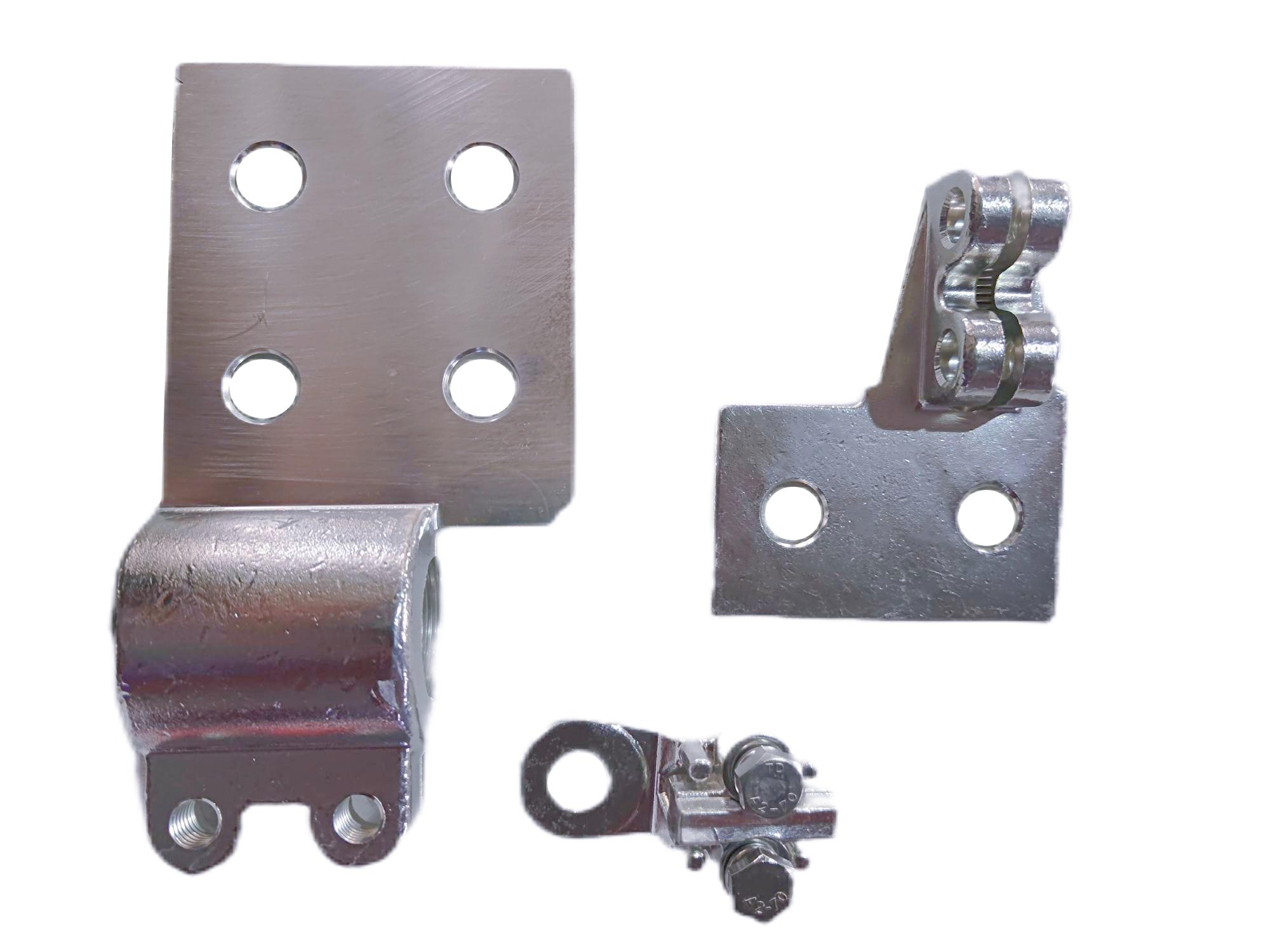
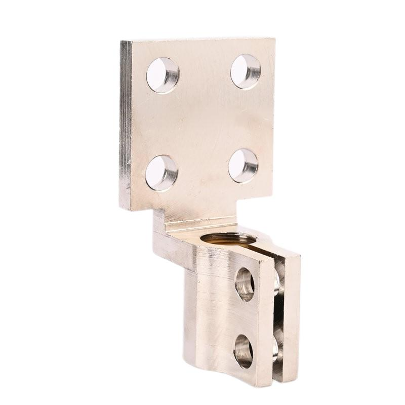
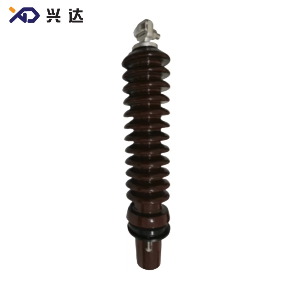
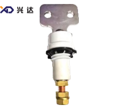
A transformer brass flag bushing connector is a cast or machined brass conductive terminal that interfaces directly with the threaded stud of transformer low‑voltage or medium‑voltage porcelain, epoxy or composite bushing. The component gets its “flag” name from its flat, spade‑shaped outer plate, which features 2‑4 pre‑drilled mounting holes for bolting to copper busbars or cable lugs. The lower threaded or split‑clamp body fastens onto the bushing’s conductive stem, establishing continuous electrical continuity from transformer winding leads out to external power circuits.
Main structural parts of a typical brass flag bushing connector:
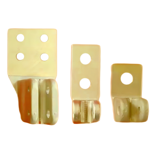
Flag Spade Plate: Flat brass connecting plate with mounting holes; connects to external busbar or cable terminal. Hole quantity includes 2‑hole, 3‑hole and 4‑hole configurations for different current ratings.
Clamping Body: Threaded internal bore or split clamp structure, matches bushing stud thread sizes such as M12, M16, M20, M24, M30, M48.
Fastening Hardware: High‑strength bolts, nuts and lock washers to maintain consistent torque for low‑resistance contact surfaces.
Surface Finishing Layer: Tin‑plated or silver‑plated anti‑oxidation coating applied over brass base material for corrosion resistance and improved conductivity at contact interfaces.
While brass flag bushing connectors are mostly deployed for low‑voltage distribution transformers from 1 kV up to 36 kV, high‑current variants can handle rated current ranges from 250 A up to 4500 A for medium‑power transformer units.
Core Functions of Brass Flag Bushing Connector in Transformer Systems
Every brass flag bushing connector fulfills three non‑negotiable core functions inside transformer power circuits. Poor performance of any function will introduce operational risk for the whole transformer system.
1. Electrical Conductive Connection
The primary purpose is to transfer rated load current between transformer internal windings and external distribution networks. The brass alloy material ensures adequate electrical conductivity to minimize contact resistance and resist local overheating under continuous load conditions. Proper surface treatment further reduces contact resistance across bolted joint interfaces.
2. Mechanical Strength and Anti‑Loosening Performance
Transformer operation generates vibration from core magnetostriction, plus huge electromagnetic short‑circuit force during fault events. Brass flag bushing connectors provide rigid mechanical clamping to hold busbar connections firmly in position, preventing bolt loosening, joint displacement or terminal separation that could cause arc discharge and equipment damage.
3. Environmental Corrosion Resistance
Installed mostly outdoors in substation yards or on‑pole distribution transformers, flag terminals face humidity, rain, industrial pollution, salt spray in coastal regions. Brass substrate combined with tin‑plating or silver‑plating surface treatment slows oxidation and galvanic corrosion, maintaining stable contact performance over decades of service life.
Material Specifications & Surface Treatment Options
Material selection determines the electrical performance, mechanical strength, corrosion resistance and total cost of transformer brass flag bushing connectors. Industry‑accepted raw material grades and surface finishing options are shown below.
Material Option
Material Grade
Key Characteristics
Typical Application Scenario
Lead‑Free / Lead‑Alloy Brass | CuZn40Pb2, C36000 | Excellent machinability, moderate conductivity, good tensile strength, cost‑effective | Standard distribution transformer brass flag terminals, DIN 43675 compliant products |
High‑Strength Brass Alloy | C26000 Cartridge Brass | High mechanical toughness, anti‑fatigue under thermal cycles | Heavy‑duty transformers with frequent load fluctuation |
Tin‑Plated Brass | Brass base + tin electroplating | Anti‑oxidation, anti‑tarnish, reduces contact resistance, prevents surface corrosion | General outdoor installation, most global standard projects |
Silver‑Plated Brass | Brass base + silver plating | Lowest contact resistance, outstanding high‑current anti‑heating performance | High‑current terminals above 1600 A, high‑reliability substation projects |
Bare Uncoated Brass | Raw machined brass | Low unit cost; prone to surface oxidation in humid environment | Indoor dry‑location transformer applications only |
Brass flag bushing connectors are frequently compared with pure copper flag terminals. Brass has lower raw‑material cost than copper, with sufficient mechanical rigidity, while pure copper delivers higher electrical conductivity for ultra‑high‑current applications. Many transformer‑engineering teams select brass flag connectors for low‑and‑medium‑current projects to balance total cost and operational reliability.
Key Technical Parameters of Transformer Brass Flag Bushing Connector
The following table lists widely‑adopted standard technical specifications for industry‑general transformer brass flag bushing connectors. These parameters serve as reference data for transformer design, component selection and spare‑part replacement.
Parameter Category
Specification Range
Remarks
Rated Voltage Level | 1 kV, 12 kV, 24 kV, 36 kV | Matches transformer bushing rated voltage |
Rated Continuous Current | 250 A, 400 A, 630 A, 1000 A, 1600 A, 2000 A, 3150 A, 4500 A | Cross‑section area of flag plate determines current carrying capacity |
Matching Bushing Stud Thread | M12, M16, M20, M24, M30, M40, M48 | DIN, ANSI and EN standards adopt different thread specificationsAlibaba.co... |
Flag Plate Mounting Hole Layout | 2‑hole, 4‑hole | 2‑hole for low‑current; 4‑hole for high‑current heavy busbar connection |
Standard Compliance | DIN 43675, DIN 42533, EN 50180, IEC 60137, ANSI C119.4 | Different regional markets require corresponding standard compliance |
Working Ambient Temperature | ‑40 °C ~ +85 °C | Short‑term temperature rise under overload follows IEC thermal‑rise limits |
Typical Surface Treatment | Tin plating / Silver plating | Silver plating recommended for >1000 A rated current |
Installation Torque Range | 25 N·m to 80 N·m | Torque value depends on thread size and current rating; over‑torque risks thread damage |
Customization Support | Custom hole spacing, custom thread size, custom flag dimension | Non‑standard dimensions available against engineering drawings |
Core Advantages of Transformer Brass Flag Bushing Connector
Flexible Multi‑Hole Mounting DesignThe flag‑style flat plate with multiple bolt holes allows installers to adapt to different busbar widths, cable‑lug sizes and connection layouts without modifying transformer bushing hardware. This feature greatly simplifies on‑site installation work for transformer‑erection contractors.
Balanced Mechanical Performance and Cost‑EfficiencyBrass alloy provides higher mechanical rigidity than pure copper, resisting deformation under clamping torque and short‑circuit force. Compared with copper flag terminals, brass solutions deliver significant material‑cost reduction while satisfying most distribution‑transformer technical requirements.
Strong Anti‑Corrosion Performance with Surface PlatingTin‑plated or silver‑plated brass flag terminals resist atmospheric corrosion, humidity and salt‑fog erosion, suitable for coastal areas, industrial zones and polluted outdoor substation environments. Good anti‑tarnish performance maintains stable contact resistance across decades of service cycle.
Wide‑Range Standard CompatibilityMass‑produced brass flag bushing connectors follow DIN, EN, ANSI and IEC specifications, interchangeable with most mainstream transformer‑bushing products globally. This compatibility simplifies spare‑parts procurement for global transformer‑manufacturers and utility operators.
Excellent Vibration‑Resistant Connection StabilityCombination of split‑clamp or threaded‑socket structure plus lock‑washer fasteners effectively counteracts vibration‑caused loosening on pole‑mounted distribution transformers, avoiding the high‑risk failure mode of loose terminal connections.
Main Application Fields of Brass Flag Bushing Connector
Transformer brass flag bushing connectors are essential power‑system hardware components, applied across multiple segments of power‑transmission and power‑distribution infrastructure:
Distribution Transformers: On‑pole and pad‑mounted distribution transformers for urban and rural power‑grid networks; low‑voltage side bushing terminals represent the largest‑volume application scenario.
Medium‑Voltage Power Transformers: Auxiliary low‑voltage terminals of medium‑power substation transformers for industrial power plants and public‑utility substations.
Special‑Purpose Transformers: Control transformers, rectifier transformers, furnace transformers and reactor bushing conductive terminals.
Transformer After‑Sales Replacement & Maintenance: Spare‑part replacement for old‑generation transformers deployed in European, Southeast‑Asian, South‑American markets that follow DIN or ANSI standards.
Renewable‑Energy Power‑Plants: Step‑up distribution transformers inside solar‑farm and wind‑farm power collection systems.
Critical Selection Guidelines for Brass Flag Bushing Connector
Improper specification selection is a top cause of field‑level overheating and failure. When specifying transformer brass flag bushing connectors, engineers should evaluate the following dimensions comprehensively:
Match Rated Current and Voltage with Transformer BushingNever select a flag connector with lower rated current than transformer nominal output current. Under‑rated terminals generate excessive heat during normal operation, accelerating surface oxidation and triggering hot‑spot risks. Voltage rating must fully match the bushing’s rated voltage level.
Confirm Thread Size of Bushing Conductive StudThread mismatch will cause installation difficulty, thread stripping and unreliable clamping. Confirm whether the bushing follows DIN metric thread or ANSI inch‑thread standards before ordering replacement flag connectorsAlibaba.co....
Select Suitable Surface Treatment According to Operating EnvironmentFor inland ordinary‑atmosphere locations, tin‑plated brass meets requirements. For coastal salt‑spray environment or heavy‑pollution industrial zones, silver‑plated brass is recommended to enhance anti‑corrosion and anti‑oxidation capacity. Bare brass terminals are only allowed for indoor dry‑location use.
Check Busbar Hole‑Spacing CompatibilityVerify hole diameter and hole‑to‑hole spacing of flag spade plate to match connected copper busbar or cable lug hole layout, avoiding forced offset assembly which will produce uneven contact pressure and high local resistance.
Follow Regional Standard RequirementsEuropean‑market projects prioritize DIN 43675 and EN 50180 standards; North‑American‑market projects follow ANSI C119.4 requirements. Export‑oriented transformer projects must specify corresponding compliance standards in technical documents.
Installation Best Practices for Brass Flag Bushing Connector
Even high‑quality brass flag bushing connectors may develop faults caused by incorrect field installation. Follow these key installation recommendations:
Perform LOTO (Lock‑Out Tag‑Out) safety procedures; confirm transformer is fully de‑energized before any terminal installation work.
Clean all contact surfaces of brass flag connector, bushing stud and busbar lugs, removing dust, grease, oxidation films or residual anti‑rust coating. Poor surface cleaning is a primary source of high‑contact‑resistance heating.
Apply appropriate installation torque per design specification. Excessive torque will crack brass thread or deform flag plate; insufficient torque creates loose joints and contact overheating. Use calibrated torque wrenches for critical substation‑transformer installation.
Install lock washers or spring washers together with flat washers to mitigate loosening risk caused by equipment vibration and thermal expansion‑contraction cycles.
Avoid forced misalignment assembly. Do not bend or twist the brass flag plate to compensate for busbar positional deviation; adjust busbar layout instead. Permanent deformation of flag plate reduces clamping contact area.
After installation completion, maintain proper phase‑to‑phase clearance between adjacent flag terminals to prevent phase‑to‑phase short‑circuit risk under high‑humidity or pollution conditions.
Common Failure Modes & Root‑Cause Analysis
Field‑observed failure modes for transformer brass flag bushing connectors and their typical root‑causes are summarized below:
Failure Phenomenon
Primary Root‑Cause
Local overheating, discoloration or burn mark on flag plate | Insufficient installation torque; oxidized contact surface; under‑rated current specification; loose fasteners from vibration |
Thread stripping or flag‑plate permanent deformation | Over‑torque during installation; forced misalignment assembly; mechanical impact during transportation |
Heavy surface corrosion and oxidation | Bare brass used in outdoor humid or salt‑spray environment; damaged plating layer; long‑term exposure to industrial corrosive gas |
Bolt self‑loosening under operating conditions | Missing lock‑washer hardware; severe continuous vibration from transformer core; thermal cycling fatigue |
Crack on flag‑plate corner | Material defect; mechanical shock during shipping or on‑site lifting; excessive stress from rigid busbar layout |
Most field failures are not material‑quality defects, but originate from improper selection, careless installation or unsuitable operating‑environment matching.
Routine Inspection and Maintenance Guidance
Regular inspection extends service life of brass flag bushing connectors and detects hidden faults before transformer‑trip events:
Visual Inspection (Routine Site Patrol)Check for discoloration, burn marks, corrosion, plating peeling, crack or deformation on flag connector surface. Confirm all bolts and nuts remain in place with no visible loosening. Inspect dust and pollutant accumulation on terminal surface, clean surface contaminants in polluted regions periodically.
Thermal MonitoringUse infrared thermal‑imaging equipment to scan brass flag bushing connectors during peak‑load periods. Abnormal temperature rise compared with adjacent‑phase terminals indicates high‑resistance joint risk that requires timely maintenance treatment.
Torque Re‑CheckFor pole‑mounted distribution transformers exposed to long‑term vibration, perform periodic torque re‑check for flag‑connector fastening bolts. Retorque to the rated torque value when bolt loosening is detected.
Replacement PrincipleReplace brass flag bushing connector once permanent deformation, crack, heavy corrosion or burn damage appears. Do not reuse deformed or heavily oxidized terminals even after surface polishing. When replacing spare‑parts, strictly match voltage, current rating, thread dimension and surface‑treatment specification of original component.
Conclusion
Transformer brass flag bushing connector is a small‑size yet high‑impact conductive component of power‑transformer bushing systems. Its flag‑spade multi‑hole‑mount design delivers flexible busbar‑connection capability, balanced mechanical strength and favorable total‑cost performance for distribution‑transformer projects across global markets. Correct material‑grade selection, surface‑treatment specification, standardized installation and periodic inspection jointly ensure low‑resistance, stable long‑term operation. When specifying brass flag bushing connectors, design engineers must fully consider rated electrical parameters, bushing‑thread matching, local‑market‑standard requirements and site environmental conditions to avoid premature field failure and improve overall transformer reliability.
Categories
Contact Us
Contact: Tianjin Delda Trading Co., Ltd
WhatsApp: +86 13662056855
Tel:
E-mail: solomon20210701@tjxddq.com
Add: Unit‑101, Workshop 3, Bozhong Automobile Industrial Park, No.5 Xianghui Road, Intersection of Xianghui Road and Gaoying Road, Beizhakou Town, Jinnan District, Tianjin, China