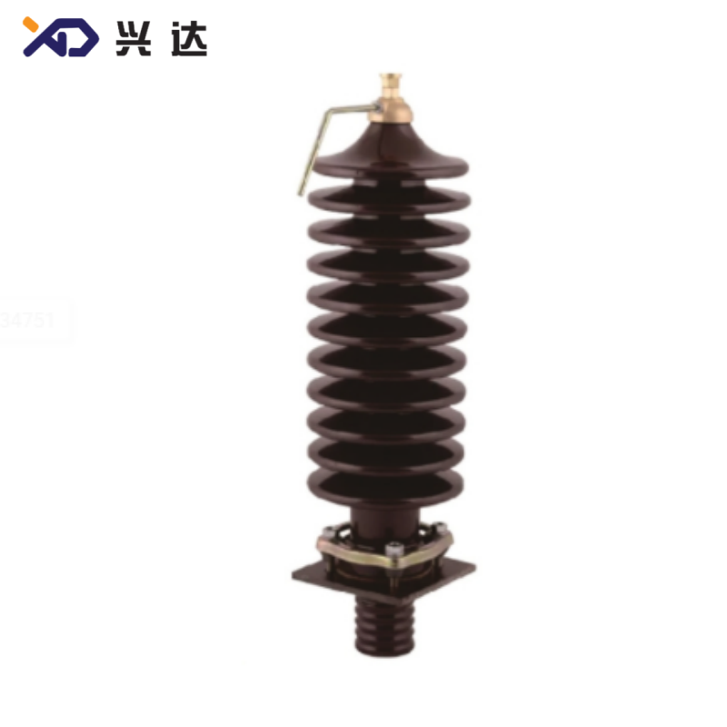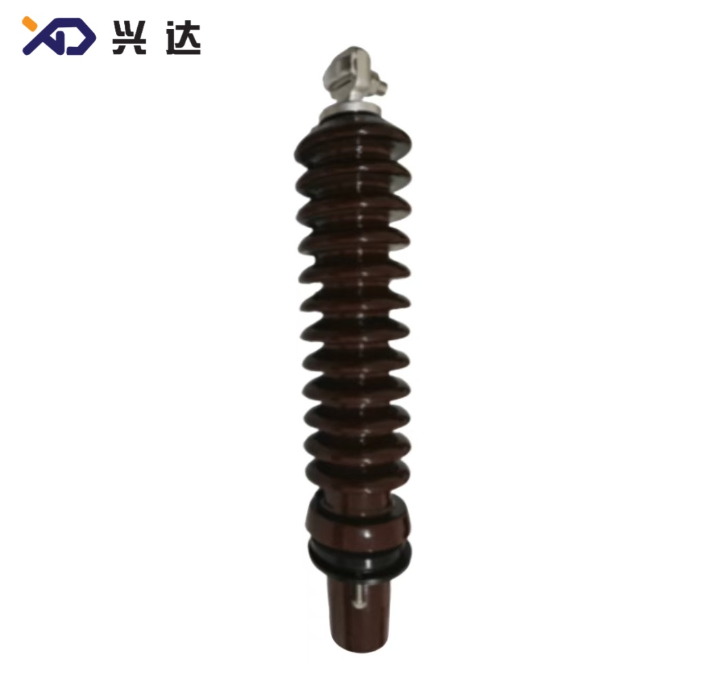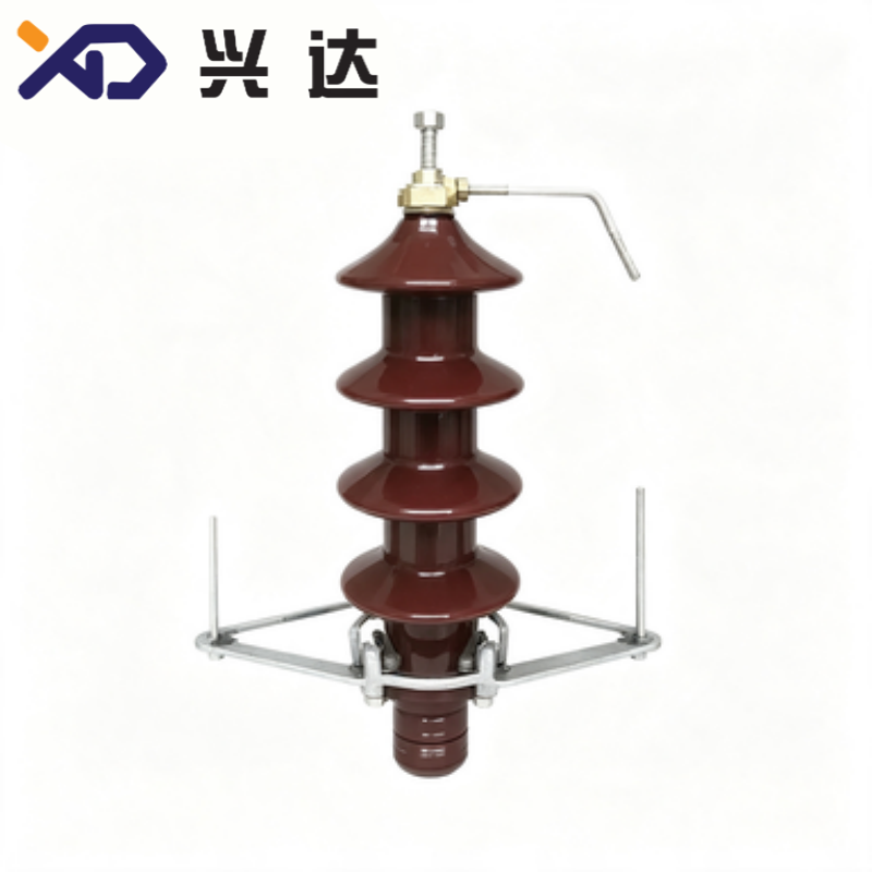
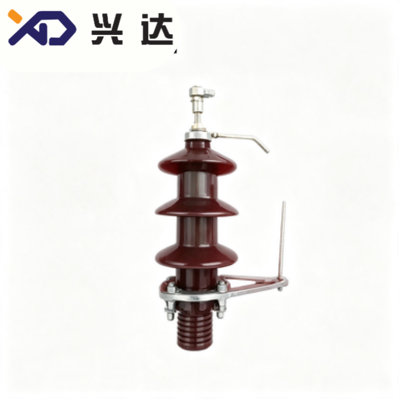
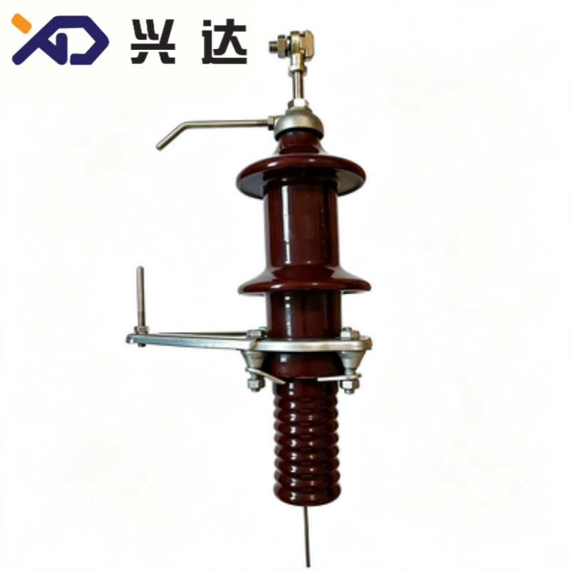

DIN transformer bushing refers to transformer through‑insulation components manufactured according to German DIN standards, widely adopted for oil‑immersed distribution transformers and medium‑size power transformers across Europe, Middle East, Africa and many Asia‑Pacific regions that follow IEC technical frameworks. As a critical transformer accessory, the DIN transformer bushing performs two core missions. First, it provides reliable electrical insulation for live conductors passing through the grounded metal transformer tank wall. Second, it delivers stable mechanical support for external connection terminals, bus bar joints and cable lugs.
Common DIN standard serial codes for transformer bushings include DIN 42530, DIN 42531, DIN 42532, DIN 42533 and DIN 42539. These specifications cover low‑voltage and medium‑voltage working conditions from 1 kV up to 36 kV, with continuous current ratings ranging from 250 A to 6300 A. Most conventional DIN transformer bushings use glazed porcelain as outer insulating housing, paired with brass or copper central conductive rods, oil‑resistant rubber sealing gaskets and metal mounting flange assemblies. Half of the bushing structure stays immersed inside transformer mineral oil, and the other half exposes to open‑air indoor or outdoor operating environments.
It is important for procurement and maintenance engineers to understand that DIN transformer bushing cannot be directly interchanged with ANSI standard bushing. Obvious dimensional gaps exist in tank opening size, flange bolt‑circle layout, terminal thread specifications and creepage distance design. Improper cross‑standard replacement will cause assembly mismatch, oil leakage risk and hidden insulation failure hazards. Users must verify standard compliance for new transformer production, equipment retrofitting and spare‑part procurement work.
A complete DIN transformer bushing consists of multiple modular parts. Modular structural design facilitates field inspection and partial component replacement during transformer overhaul without discarding the whole bushing unit.
Glazed Porcelain Insulator Housing: Brown glazed porcelain forms the primary outer insulation shell. The smooth glaze layer strengthens hydrophobic property, slows dust accumulation, resists ultraviolet radiation and atmospheric corrosion. Shed shapes are precisely calculated to achieve required creepage distance and prevent surface flashover under humid, foggy or polluted site conditions.
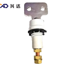
Central Conductor Assembly: High‑conductivity copper or brass rod transfers load current from transformer internal winding leads to external connection terminals. Conductor cross‑section strictly matches rated continuous current and short‑circuit withstand capacity to avoid abnormal overheating under normal operation and fault conditions. Flat flag‑type brass terminals are frequently equipped at the top for convenient bus bar installation.
Oil‑Resistant Sealing Gasket Set: Nitrile rubber gaskets are installed between porcelain insulator, metal flange and transformer tank surface. These sealing elements stop transformer mineral oil from leaking outward and block external moisture and dust from penetrating into transformer tank. Damaged or aging gaskets represent one of the top failure sources for DIN transformer bushing in real‑world service.
Mounting Flange: Metal flange offers standardized mounting interface for installation on transformer tank openings. DIN documents define unified tank hole dimension, bolt‑circle position and gasket compression requirement for each model number.
Fastening Hardware: Nuts, flat washers and spring washers maintain uniform compression force for sealing surfaces and keep terminal connectors under stable contact pressure. Too low torque causes bad electrical contact and local overheating; excessive torque may crack porcelain housing.
Material performance directly determines insulation stability, anti‑aging capacity and overall service life of DIN transformer bushing. The following table compares mainstream material combinations used for standard DIN transformer bushing products.
Component Section
Common Material
Core Performance Advantages
Practical Limitations
Outer Insulating Shell | Glazed Porcelain | High compressive mechanical strength, stable dielectric performance, strong UV resistance, long working cycle, low aging rate under normal atmosphere | Relatively heavy weight; easy to crack under violent mechanical impact; higher flashover risk in heavy‑pollution industrial zones |
Outer Insulating Shell | Silicone Rubber Composite | Light unit weight, excellent anti‑pollution and hydrophobic recovery performance, good tolerance for salt fog and chemical dust | Higher production cost; needs careful protection in transportation and installation processes |
Central Current‑carrying Rod | Brass / Copper | Low electrical resistivity, good thermal conductivity, easy terminal machining, reliable contact performance for bus bar connection | Copper raw material brings higher component cost |
Sealing Gasket Parts | Nitrile Butadiene Rubber | Superior oil‑resistant characteristic for long‑time contact with transformer mineral oil, moderate ambient temperature adaptability | Performance declines under persistent ultra‑high temperature or heavy ozone exposure |
DIN 42530 mainly covers low‑voltage transformer bushings for 1 kV to 3 kV, widely applied for the low‑voltage side of distribution transformers. DIN 42531, DIN 42532 and DIN 42533 specify medium‑voltage bushing parameters from 12 kV to 36 kV for power distribution equipment. The table below lists representative general‑purpose DIN transformer bushing models and key technical parameters for industry reference. All figures reflect common reference values, and actual dimensions shall follow official standard documents or component drawings. Custom voltage and current grades can be realized for special transformer project demands.
DIN Standard Code
Model
Rated Voltage
Rated Continuous Current
Tank Hole Diameter
Main Terminal Thread
DIN 42530 | DT 1/250 | 1 kV | 250 A | 45 mm | M20 |
DIN 42530 | DT 1/630 | 1 kV | 630 A | 45 mm | M20 |
DIN 42530 | DT 1/1000 | 1 kV | 1000 A | 56 mm | M30 |
DIN 42530 | DT 1/2000 | 1 kV | 2000 A | 70 mm | M42 |
DIN 42531 | 10NF250 | 12 kV | 250 A | 78 mm | M12 |
DIN 42532 | 10NF630 | 12 kV | 630 A | 90 mm | M20 |
DIN 42532 | 20NF630 | 24 kV | 630 A | 95 mm | M24 |
DIN 42532 | 30NF630 | 36 kV | 630 A | 110 mm | M30 |
Metric‑Standardized Interchangeability: Products complying with DIN standards support cross‑supplier component interchangeability for transformer maintenance and spare‑part replacement, lowering procurement complexity for power asset operators. Metric dimension system perfectly fits European and IEC‑aligned transformer design ecosystems.
Modular Component Structure: Separable porcelain housing, conductive rod and rubber gaskets allow targeted single‑part replacement instead of full‑unit discard, effectively cutting long‑term operational cost for large transformer fleet management.
Optimized for Oil‑Immersed Operation: Structural parameters are tuned for long‑term partial immersion in mineral transformer oil. Reasonable sealing design reduces oil leakage and moisture‑intrusion probability when installation torque follows technical specifications.
Flexible External Connection Solution: Top‑mounted flat brass flag terminals support direct connection with copper bus bars, simplifying on‑site wiring work for distribution stations and industrial power facilities.
Wide Application Coverage: The complete DIN bushing portfolio spans low‑voltage to medium‑voltage ranges, matching small‑size distribution transformers and medium‑capacity power transformers for utility grid and private industrial power supply systems.
DIN transformer bushings serve as indispensable transformer accessories across multiple power‑related fields:
Oil‑immersed distribution transformers for urban and rural public utility power grid, both low‑voltage side and medium‑voltage side
Industrial oil‑filled transformers for factory internal power supply systems
Auxiliary power step‑up transformers used in solar power stations and wind farm projects
Refurbishment and spare‑part replacement projects for legacy European‑standard transformer equipment
Indoor and outdoor substation transformers that satisfy IEC and DIN electrical requirements
Before finalizing DIN transformer bushing selection for any project, engineers need to confirm five key parameters: rated operating voltage, rated continuous current, transformer tank opening dimension, site environmental pollution class and transformer insulating medium type.
Correct installation directly decides sealing reliability and whole‑service‑life performance of DIN transformer bushing. Several universal industry operation rules apply for field installation work.
First, complete full‑range component inspection before assembly. Check porcelain insulator surface for cracks, chips or glaze damage; examine rubber gaskets for aging, crack or permanent deformation; verify conductive rod surface and thread integrity. Any defective component must not be mounted onto transformer tank.
Second, keep transformer tank mounting surface clean, flat and free of burrs, paint residues or metal debris. Uneven tank surface will cause partial gasket compression and trigger oil leakage after long‑period running.
Third, place sealing gasket at correct position, insert bushing into tank opening, and tighten flange nuts with evenly distributed recommended torque value. Never apply excessive torque which may crack porcelain insulator housing.
Fourth, finish external terminal connection. Align bus bar contact face with flag‑shaped brass terminal, use matched fasteners and apply proper torque to guarantee low‑resistance contact. Do not pull or twist bushing main body when adjusting bus bar position. External mechanical stress transmitted from bus bars may break porcelain shell or destroy internal sealing construction.
After installation work finishes, perform oil‑leakage inspection. Keep transformer under normal operating pressure and observe gasket joint positions for oil seepage traces.
Even well‑manufactured DIN transformer bushing may develop faults under long‑term combined electrical, thermal and environmental stress. Understanding common failure patterns helps maintenance teams arrange rational inspection cycles.
Transformer Oil Leakage: Most field failures come from sealing system degradation. Rubber gaskets gradually age under continuous heat and transformer‑oil contact. Uneven fastening torque during previous installation is another frequent inducing factor. Once oil leakage occurs, relevant transformer equipment should be shut down and the full gasket set must be replaced.
Porcelain Insulator Crack: Cracks may generate during transportation, wrong installation torque or external mechanical impact. Micro‑cracks permit moisture to enter inner structure, resulting in insulation decline and potential flashover accident. Any visible crack requires immediate component replacement.
Terminal Joint Overheating: Insufficient fastening torque or oxidized contact surface creates high contact resistance. Load current produces excessive heat which accelerates aging of nearby sealing and insulating materials. Regular infrared thermal scanning can detect abnormal temperature rise on bushing terminals in advance.
Surface Pollution‑Induced Flashover Risk: Dust, salt spray or industrial contaminant accumulates on porcelain shed surface. Under foggy or wet weather conditions, surface conductivity rises and flashover accident may take place. For heavy‑pollution operation sites, select DIN transformer bushing with enlarged creepage distance or composite insulating housing, and implement periodic surface cleaning work.
Routine maintenance suggestions: Conduct visual inspection for oil leakage and porcelain damage during regular transformer check cycles. Apply infrared thermal imaging technology to monitor terminal operating temperature. Replace rubber sealing gaskets during major transformer overhaul regardless of apparent gasket surface condition.
Many procurement personnel confuse DIN transformer bushing and ANSI transformer bushing. The table below presents key comparison points.
Comparison Item
DIN Transformer Bushing
ANSI Transformer Bushing
Main Application Market | Europe, Middle East, Asia‑Pacific IEC‑following regions | North America and areas adopting US power standards |
Governing Standard Documents | DIN 42530, DIN 42531, DIN 42532, aligned with IEC 60137 | IEEE C57.19.01 |
Dimension Measuring System | Metric measurement | Inch‑based imperial dimension |
Tank Mounting Interface | DIN‑defined tank hole and flange bolt‑circle pattern | ANSI‑specified bolt‑circle and tank opening dimension |
Terminal Structural Style | Metric‑threaded rod plus flat flag brass terminal | Stud‑type terminal or special draw‑lead terminal design |
Direct Mechanical Interchangeability | Cannot swap directly without transformer‑tank modification | Cannot swap directly without transformer‑tank modification |
Before confirming DIN transformer bushing specifications for new manufacturing or replacement tasks, go through these check items to avoid specification‑mismatch mistakes:
Confirm rated operating voltage matches actual transformer winding voltage grade.
Confirm rated continuous current meets maximum transformer load requirement; also verify short‑circuit current withstand rating.
Measure or check transformer tank opening inner diameter and flange mounting dimension.
Evaluate site environmental pollution level and select corresponding creepage distance and insulator housing material.
Confirm gasket material compatibility with transformer insulating medium, such as special gaskets for ester‑based transformer oil.
Check terminal connection form matches on‑site bus bar or cable lug installation requirement.
DIN transformer bushing represents a fundamental transformer accessory for IEC‑standard power equipment. Thorough understanding of DIN standard serial codes, material characteristics, specification parameters, installation requirements and common failure mechanisms assists transformer original equipment manufacturers, procurement engineers and maintenance technicians to finish correct component selection and reduce hidden risks inside power systems. Along with global power‑grid asset renewal progress, DIN‑compliant transformer bushings maintain steady market demand for new transformer production and old‑equipment refurbishment projects.
Contact: Tianjin Delda Trading Co., Ltd
WhatsApp: +86 13662056855
Tel:
E-mail: solomon20210701@tjxddq.com
Add: 55-302 Xiaoyuan New Village, Tianjin Economic and Technological Development Zone, China