gas relay
Gas Relay: Complete Technical Guide for Oil‑Immersed Transformers
Gas Relay: Complete Technical Guide for Oil‑Immersed Transformers
What is Gas Relay
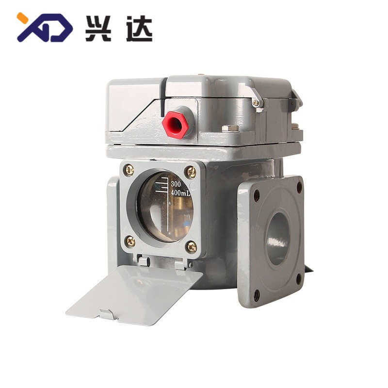
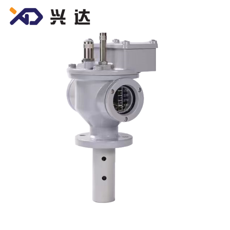
According to general power industry standards, gas relay is usually mandatory for oil‑immersed transformers above 800 kVA, and also required for on‑load tap‑changer assemblies. It can capture incipient internal faults which cannot be easily identified by electrical differential protection relays. Built‑in sight glass and gas sampling cock allow field technicians to collect fault gas samples for dissolved gas analysis (DGA), supporting accurate fault diagnosis without opening transformer tank.
Core Structure and Operating Principle
- Light‑gas alarm operation: Minor faults generate gas that accumulates in the top chamber. Collected gas displaces insulating oil inside relay housing and lowers local oil level, making the float‑cup sink. The built‑in magnet triggers magnetic reed switch and sends remote alarm signal to control room, reminding maintenance personnel to conduct inspection without immediate power cut. Typical light‑gas action gas volume ranges from 200 mL to 300 mL. Air ingress during oil filling or slow oil leakage can also trigger light‑gas alarm.
- Heavy‑gas trip operation: Severe internal faults produce huge volumes of gas in a very short time, pushing high‑speed oil surge toward conservator. Oil flow strikes the internal baffle plate, driving heavy‑gas contact closure and activating circuit‑breaker trip loop to isolate transformer from power grid. Typical operating oil‑flow velocity ranges 0.6‑1.5 m/s according to nominal pipe diameter.
Critical installation note: Gas relay must be installed horizontally and follow the oil‑flow direction arrow printed on housing. The connecting pipe shall keep a 1%‑1.5% upward slope toward conservator, ensuring all fault gas flows smoothly into relay chamber without trapped gas pockets.
Main Classification of Gas Relay
| Gas Relay Type | Core Features | Contact Configuration | Typical Application |
|---|---|---|---|
| Standard Float‑cup Gas Relay | Float‑cup for light‑gas detection, baffle for heavy‑gas oil surge | Light‑gas alarm contact + heavy‑gas trip contact | General distribution transformers and medium power transformers |
| Anti‑misoperation Gas Relay | Optimized baffle structure, resisting transient oil surge disturbance | Alarm and trip contacts | Large‑capacity power transformers, substation main transformers |
| Auxiliary‑signal Gas Relay | Extra dry contacts for remote status feedback | Alarm, trip, running‑status signal | Intelligent unattended substations, remote monitoring projects |
| Tap‑changer Dedicated Gas Relay | Compact dimension, fast response for tap‑changer internal faults | Alarm and trip contacts | Oil‑immersed on‑load tap‑changer unit |
Key Technical Specification Tables
Table 1: Nominal Diameter Matching with Transformer Capacity
| Nominal Diameter DN (mm) | Suitable Transformer Capacity | Light‑gas Action Gas Volume | Heavy‑gas Trip Oil Flow Velocity | Contact Rating |
|---|---|---|---|---|
| DN50 | 800 kVA‑2500 kVA | 200‑300 mL | 0.8‑1.2 m/s | AC 220V, 5A |
| DN80 | 3150 kVA‑10000 kVA | 200‑300 mL | 1.0‑1.3 m/s | AC 220V, 5A |
| DN100 | Above 12500 kVA power transformer | 250‑300 mL | 1.1‑1.5 m/s | AC 220V, 5A |
Practical note: Trip oil‑flow velocity can be calibrated in factory. Improper setting will result in false tripping or refusal to act under real fault conditions.
Table 2: Gas Relay Action Cause and On‑Site Handling Guidance
| Protection Action | Main Trigger Causes | Recommended Field Handling |
|---|---|---|
| Light‑gas Alarm | Local overheating, partial discharge, air ingress during oil filling, minor insulation aging, slow oil leakage | Collect gas sample, perform DGA analysis, check sealing and oil filling condition, do not restart transformer blindly |
| Heavy‑gas Trip | Winding short‑circuit, internal arc fault, core ground fault, serious oil surge caused by catastrophic failure | Keep transformer de‑energized; internal inspection is mandatory before re‑closing circuit breaker |
Gas Relay Selection Guidelines
- Transformer capacity and pipeline nominal diameterMatch gas relay DN size with the connecting pipe diameter between transformer main tank and conservator. Mismatched diameter will change actual oil‑flow velocity passing through relay and deviate heavy‑gas operating threshold. DN50 is widely used for medium‑small distribution transformers; DN80 or DN100 applies for large‑capacity power transformers.
- Contact function requirementsCommon distribution transformers adopt standard dual‑contact configuration: light‑gas for alarm only and heavy‑gas for trip. For unattended substations, select gas relay with extra auxiliary contacts to connect remote monitoring system. On‑load tap‑changer device requires dedicated tap‑changer gas relay instead of general‑purpose models.
- Environmental adaptabilityStandard gas relay works within operating temperature range of ‑40 °C ~ +85 °C. For cold‑climate regions, verify low‑temperature resistance of internal sealing gaskets to avoid gasket hardening and oil leakage. Outdoor‑installed gas relay shall have waterproof junction box to prevent water ingress and secondary‑circuit short‑circuit.
- Anti‑misoperation performanceExternal short‑circuit may generate transient oil surge and cause false heavy‑gas tripping. For large‑capacity transformers, select gas relay with optimized anti‑surge baffle, or configure proper time‑delay logic in protection control system to reduce mis‑operation risk.
Installation, Commissioning and Maintenance Best Practices
- Strictly keep horizontal installation, follow arrow mark for oil flow direction, avoid tilted installation.
- Guarantee connecting pipeline maintains upward slope toward conservator to prevent gas accumulation before relay inlet.
- After oil filling and commissioning, exhaust trapped air repeatedly through gas sampling cock, eliminating false light‑gas alarm caused by residual air.
- Complete contact function test before putting into service; verify alarm and trip loop conduction status.
- Keep junction‑box sealing intact, prevent moisture and water entering secondary‑circuit terminals.
- Do not perform welding work near installed gas relay; high temperature will damage internal float and magnetic components.
Regularly inspect flange sealing condition; replace aging oil‑resistant rubber gaskets when oil seepage occurs.
Common Faults and Troubleshooting
- Frequent false light‑gas alarm without real internal faultRoot causes: residual air trapped during oil injection, poor sealing leading to air suction, water ingress in terminal box. Solutions: exhaust trapped gas, inspect flange and gasket sealing, repair waterproof performance of junction box.
- Heavy‑gas false trippingRoot causes: improper oil‑flow velocity setting, transient oil surge caused by external short‑circuit or cooling pump start‑stop. Solutions: recalibrate operating flow‑velocity parameter, optimize protection anti‑misoperation logic.
- Contacts fail to act under real fault conditionRoot causes: float or baffle mechanical jamming, magnetic reed‑switch aging, contact oxidation. Solutions: carry out periodic preventive test, check flexible movement of internal moving parts.
- Oil leakage at flange or housingRoot causes: aging or uneven compression of sealing gaskets. Solutions: replace oil‑resistant rubber gasket, apply uniform bolt tightening torque during reassembly.
Summary
Categories
Contact Us
Contact: Tianjin Delda Trading Co., Ltd
WhatsApp: +86 13662056855
Tel:
E-mail: solomon20210701@tjxddq.com
Add: Unit‑101, Workshop 3, Bozhong Automobile Industrial Park, No.5 Xianghui Road, Intersection of Xianghui Road and Gaoying Road, Beizhakou Town, Jinnan District, Tianjin, China