Iron Core
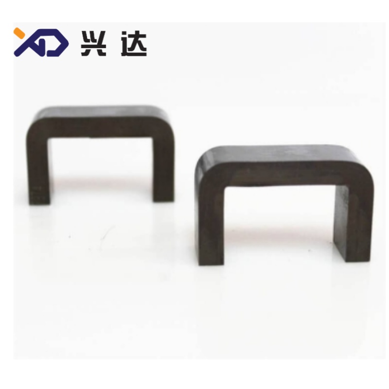
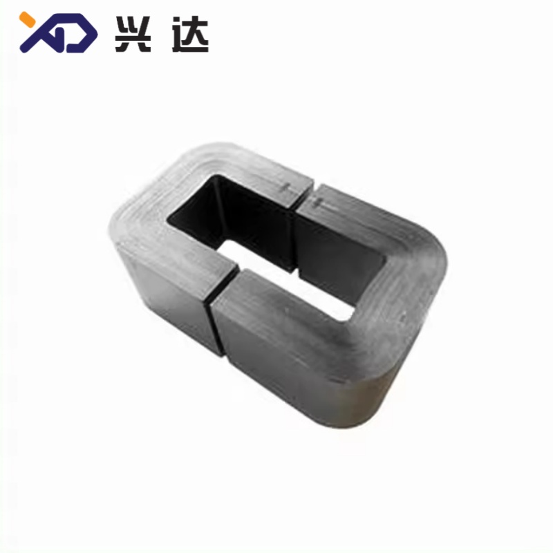
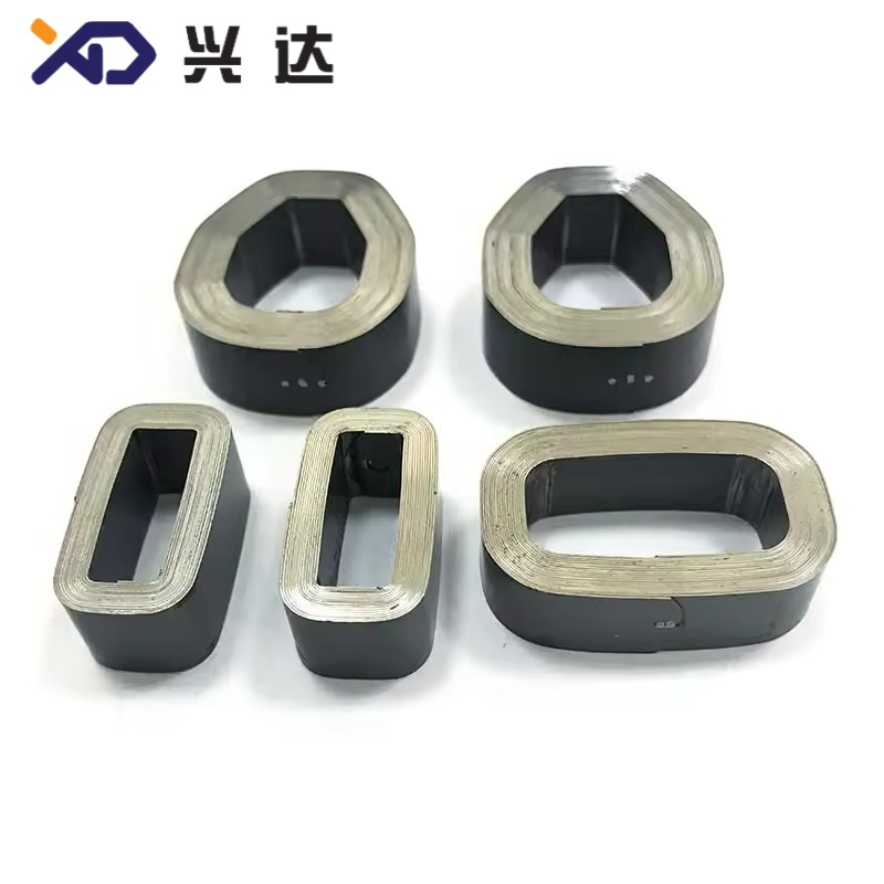
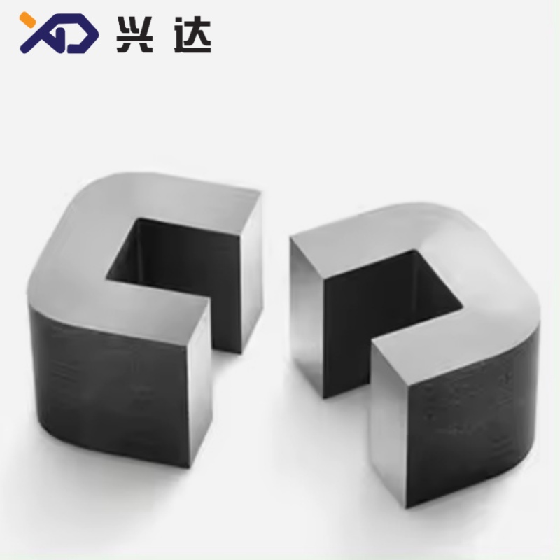
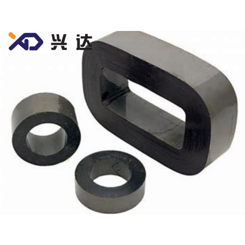
Energy Saving Laminated Silicon Steel Iron Core for Transformer Assembly
Transformer Iron Core: Complete Technical Guide for Power Equipment
Introduction to Transformer Iron Core
Transformer iron core is the magnetic circuit backbone of all power and distribution transformers, responsible for conducting magnetic flux to achieve efficient voltage transformation between primary winding and secondary winding. Many industry writings misspell this term as iron corn, while the correct technical term is transformer iron core. Without a properly engineered iron core, transformers cannot maintain high energy‑transfer efficiency and will suffer severe power waste from magnetic losses.
Most commercial transformer iron cores are assembled from stacked thin laminations of Cold‑Rolled Grain‑Oriented silicon steel, also known as CRGO steel. Each steel sheet carries an insulating coating on both sides, which suppresses eddy current loss inside the magnetic circuit. Iron core assembly sits inside transformer tank for oil‑immersed units, or inside sealed cabinet for dry‑type transformers. Its overall performance directly decides critical transformer indicators including no‑load loss, magnetizing current, operating noise level and long‑term service life.
Transformer iron core covers a broad power range, from small distribution transformers used in residential power grid up to large power transformers applied in high‑voltage substations. Material grades, lamination thickness, stacking method and joint structure are adjusted according to each project’s efficiency requirement, noise limit and budget target. Global industry widely follows IEC 60404‑8‑7 and ASTM A876 standards for silicon steel material acceptance and core performance verification.
Basic Working Principle of Transformer Iron Core
The core function of transformer iron core is to provide a low‑reluctance path for alternating magnetic flux generated by primary winding. When alternating current flows through primary coil, alternating magnetic field builds up inside iron core, then induces corresponding voltage on secondary coil. Two major energy losses take place inside iron core during normal operation: hysteresis loss and eddy current loss.
Hysteresis loss comes from repeated reversal of magnetic domains under alternating magnetic field. Material with high magnetic permeability such as CRGO silicon steel effectively reduces this type of loss. Eddy current loss originates from induced circulating current inside conductive steel material. Instead of adopting solid steel block design, manufacturers cut silicon steel into thin laminations and add inter‑sheet insulation coating. This design breaks large circulating current loops and greatly cuts heat generation caused by eddy current. Thinner lamination thickness brings lower eddy loss yet raises material processing cost and stacking workload.
Main Types of Transformer Iron Core
Transformer iron core can be classified from multiple dimensions, including structural layout, manufacturing craft and magnetic material selection. Different types fit distinct application scenarios.
Classification by Core Structure
Core‑Type Iron Core: Windings surround two vertical core limbs. This structure features simple manufacturing process, convenient winding installation and enough space for internal insulation. Widely adopted for medium and large‑capacity oil‑immersed power transformers.
Shell‑Type Iron Core: Central limb carries windings, magnetic flux flows through double side return paths. Shell‑type core delivers good anti‑leakage‑flux performance, but assembly and insulation arrangement become more complex. It applies to special high‑current transformer equipment.
Wound Toroidal Iron Core: Continuous silicon steel strip is wound into closed ring shape. Toroidal core owns extremely low magnetic leakage and quiet running performance, mostly used for small‑capacity instrument transformers and special electronic transformers.
Classification by Magnetic Material
CRGO Silicon Steel Laminated Core: Cold‑rolled grain‑oriented silicon steel represents the mainstream solution for grid transformers. Grain crystal structures align along rolling direction to achieve excellent magnetic performance. Common lamination thickness includes 0.23 mm, 0.27 mm and 0.30 mm.
HiB High‑Permeability CRGO Core: Domain‑refined high‑grade grain‑oriented steel, further reduces specific core loss. Selected for high‑efficiency energy‑saving transformer projects with strict loss index requirements.
Amorphous Alloy Iron Core: Adopts non‑crystalline thin ribbon material. It achieves ultra‑low no‑load loss compared with conventional silicon steel core. Its higher material cost restricts large‑scale application, and it gains popularity in energy‑saving distribution transformer market.
Core Structure Type
Main Material
Typical Application
Key Advantage
Main Drawback
Core‑Type Stacked Core | CRGO Silicon Steel | Distribution transformers, power transformers | Easy winding assembly, mature manufacturing process | Relatively higher magnetic leakage |
Shell‑Type Stacked Core | CRGO Silicon Steel | Heavy‑duty special transformers | Low magnetic leakage, stable mechanical strength | Complex insulation layout |
Toroidal Wound Core | CRGO Silicon Steel | Instrument transformers | Minimal flux leakage, low noise | Higher production cost for large capacity |
Amorphous Wound Core | Amorphous Metal Ribbon | Energy‑saving distribution transformer | Extremely low no‑load loss | High raw‑material cost, strict processing requirement |
Key Technical Parameters of CRGO Laminated Iron Core
Lamination thickness is one of the most important parameters for transformer iron core. 0.23 mm, 0.27 mm and 0.30 mm are three widely used thickness specifications for power distribution transformers. The table below lists general‑purpose reference parameters for these mainstream grades. All data reflect industry typical values, and actual indicators should follow material supplier test reports and international standard documents.
Lamination Thickness
Common Material Grade
Typical Specific Core Loss W/kg @1.7T 50Hz
Stacking Factor
Main Application Scenario
0.23 mm | Domain‑Refined HiB CRGO | 0.70‑0.85 | 0.95‑0.96 | High‑efficiency transformers, low‑loss requirement projects |
0.27 mm | Conventional HiB CRGO | 0.80‑0.95 | 0.96‑0.97 | General energy‑saving distribution transformers |
0.30 mm | Standard CRGO | 1.00‑1.25 | 0.96‑0.98 | Conventional distribution transformers, cost‑sensitive projects |
Note: Stacking factor describes the ratio of actual effective steel cross‑section to total stacked physical cross‑section. Insulation coating and tiny air gaps between laminations make stacking factor always less than one. Higher stacking factor means better space utilization for magnetic circuit.
Core Advantages of Qualified Transformer Iron Core
Controllable Low No‑Load Loss: Proper material grade and precise lamination processing effectively lower hysteresis loss and eddy‑current loss. For transformers running 24 hours per day in power grid, reduced no‑load loss brings remarkable long‑term energy saving benefit.
Stable Magnetic Permeability: High‑quality CRGO iron core maintains stable magnetic performance under rated operating flux density, avoids local magnetic saturation and prevents abnormal temperature rise during normal load fluctuation.
Controllable Operating Noise: Precise cutting, smooth lamination surface and reasonable clamping pressure suppress magnetostriction vibration, so as to keep transformer running noise within acceptable range for urban substations and industrial sites.
Good Mechanical Stability: Reliable clamping structure keeps laminations tightly stacked during long‑time running, prevents lamination looseness caused by vibration and thermal cycling. Stable mechanical condition avoids gradual performance degradation.
Wide Compatibility: Standard‑compliant iron core matches oil‑immersed transformer and dry‑type transformer design. Custom dimension and grade options support OEM manufacturing, equipment refurbishment and spare‑part replacement projects.
Typical Application Scenarios for Transformer Iron Core
Transformer iron core serves as indispensable magnetic component across multiple power‑related fields.
Oil‑immersed distribution transformers for urban and rural utility power grid
Medium‑size power transformers used inside industrial plants and mining facilities
Step‑up transformers for solar power stations and wind farm auxiliary power systems
Dry‑type transformers applied in high‑safety‑requirement sites such as commercial buildings and underground substations
Instrument transformers for metering and relay‑protection equipment
Refurbishment and spare‑part replacement of legacy transformer assets
When selecting transformer iron core, engineers need to confirm six key parameters: rated transformer capacity, designed operating flux density, lamination thickness, material grade, stacking‑structure requirement and site noise‑limit target.
Manufacturing and Processing Key Points
The performance of finished iron core is not only decided by raw silicon steel coil material, but also heavily influenced by processing quality.
First, slitting and shearing precision matters. Burr on lamination edge must be strictly controlled. Excessive burr will break inter‑sheet insulation coating and cause local short‑circuit between adjacent laminations, which generates extra hot‑spots inside core.
Second, inter‑sheet insulating coating must keep intact during cutting and stacking process. Damaged coating directly raises eddy‑current loss. Operators should avoid scratching steel‑sheet surface in handling procedure.
Third, stacking joint design affects overall magnetic performance. Mitred 45‑degree joint structure reduces air‑gap magnetic reluctance, which brings lower magnetizing current compared with traditional right‑angle lap joint.
Fourth, clamping pressure needs proper control. Insufficient pressure leads to loose laminations and high noise. Excessive pressure may damage insulation coating and introduce mechanical stress to silicon steel material, which degrades magnetic property.
Common Failure Modes and Maintenance Guidance
Even well‑manufactured transformer iron core may generate hidden risks under long‑term running. Understanding typical failure patterns helps maintenance teams carry out inspection and troubleshooting work.
Multi‑point Grounding Fault: Transformer iron core must maintain only one single grounding point for normal operation. Unintended second grounding point caused by metal debris, damaged insulation spacer or assembly error will form closed circulating‑current loop. This fault brings local overheating, accelerates transformer oil aging, and can be detected through DGA oil analysis and core‑ground‑current measurement.
Inter‑lamination Short Circuit: Caused by edge burr, metal foreign particles or scratched insulating coating. Partial eddy‑current loss rises and local hot‑spots appear. Slight inter‑lamination short circuit is hard to discover in early stage, and it gradually becomes worse under continuous load.
Loose Lamination Stacking: Long‑term vibration and thermal cycling may relax clamping structure. Loose laminations produce abnormal noise and vibration, and may further damage internal insulation components.
Core Over‑excitation: Occurs when actual operating flux density exceeds design limit. It causes sharp increase of core loss and temperature, threatening transformer insulation safety.
Routine maintenance recommendations: Monitor transformer no‑load loss value and noise level during regular inspection cycles. Implement DGA dissolved‑gas analysis for oil‑immersed transformers to find early‑stage core overheating risk. During major overhaul work, inspect core clamping condition, check lamination surface and remove all internal metal foreign objects.
Transformer Iron Core Selection Checklist
Before confirming iron‑core specification for new‑build transformer or replacement project, go through these check items to avoid specification mismatch.
Confirm transformer rated capacity and designed operating flux density.
Select suitable silicon steel material grade and lamination thickness according to target no‑load loss index.
Verify structural requirement: core‑type or shell‑type, mitred joint or right‑angle lap joint.
Confirm noise‑limit requirement for installation site.
Check stacking‑factor acceptance standard for finished core.
Confirm mechanical clamping and dimension tolerance requirements for downstream winding assembly.
Conclusion
Transformer iron core is the magnetic heart of power transformers. Raw‑material selection, precision processing quality and reasonable structural design jointly determine transformer’s energy‑saving effect, noise performance and long‑term operational reliability. As global power‑grid asset upgrade accelerates and energy‑efficiency standards become stricter, high‑performance CRGO laminated iron core maintains stable market demand for new transformer manufacturing and old‑equipment refurbishment. Deep understanding of core‑related technical parameters helps OEM engineers, procurement specialists and maintenance staff make correct component selection and reduce hidden risks inside power‑supply systems.
Categories
Contact Us
Contact: Tianjin Delda Trading Co., Ltd
WhatsApp: +86 13662056855
Tel:
E-mail: solomon20210701@tjxddq.com
Add: Unit‑101, Workshop 3, Bozhong Automobile Industrial Park, No.5 Xianghui Road, Intersection of Xianghui Road and Gaoying Road, Beizhakou Town, Jinnan District, Tianjin, China