Iron Core
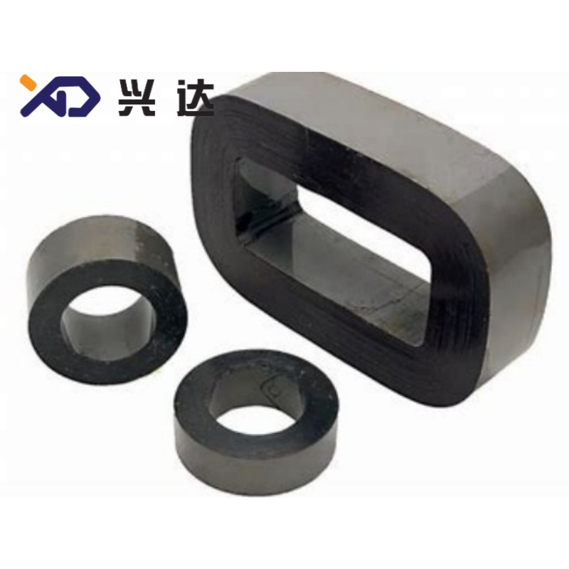
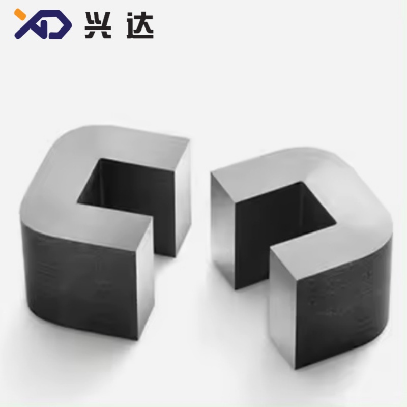
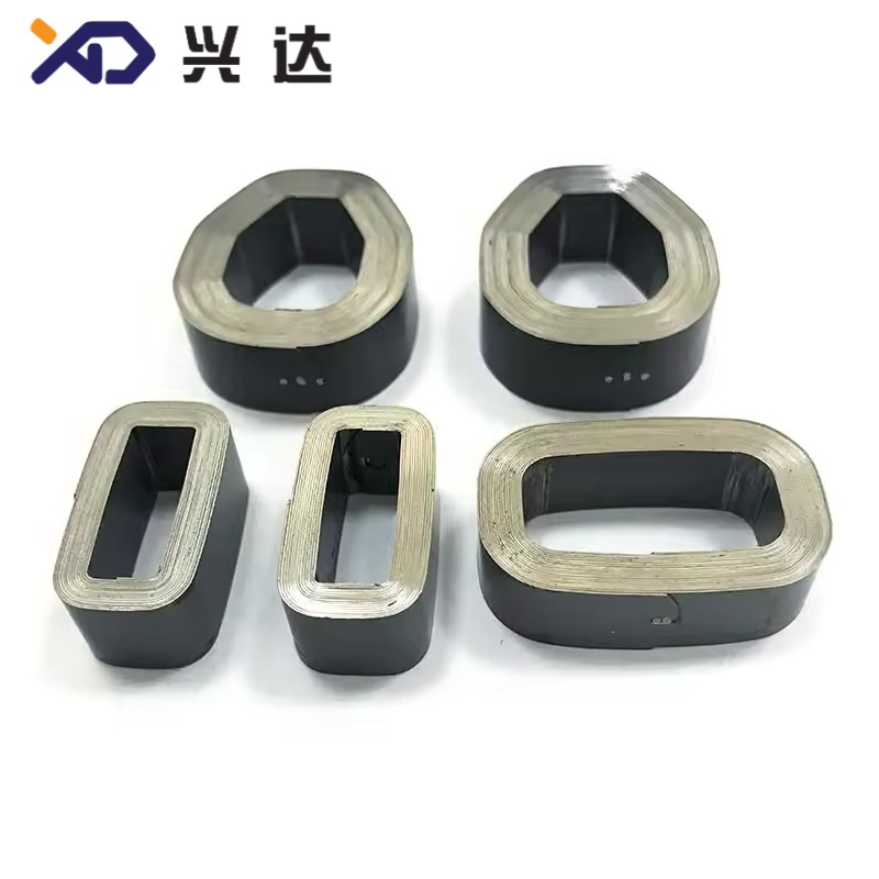
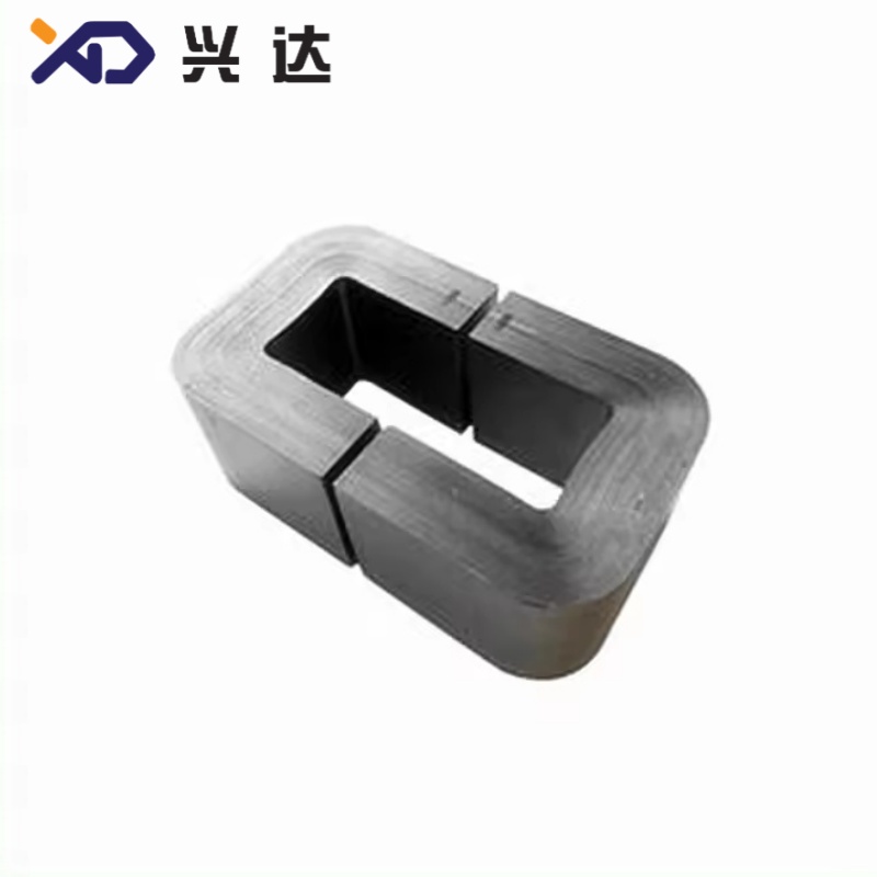
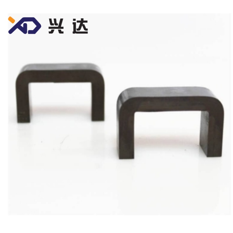
Durable Transformer Iron Core With Good Magnetic Conductivity Property
Transformer Iron Core: Complete Industry Technical Guide
Introduction to Transformer Iron Core
Transformer iron core acts as the magnetic heart for all oil‑immersed and dry‑type power transformers. It builds a closed low‑reluctance magnetic circuit to transfer magnetic flux during electromagnetic energy conversion between primary winding and secondary winding. Without a properly designed iron core, transformers suffer heavy magnetic leakage, huge energy waste and unstable voltage output.
Most modern distribution and power transformers adopt laminated iron core assembled from Cold‑Rolled Grain‑Oriented silicon steel, widely known as CRGO silicon steel. Common lamination thickness covers 0.23 mm, 0.27 mm and 0.30 mm. Thinner sheets deliver lower eddy‑current loss yet raise material and processing cost. The overall performance of transformer iron core directly decides key operating indexes including no‑load loss, magnetizing current, running noise and long‑term energy‑saving effect. Poor cutting, stacking or clamping will trigger abnormal heating, loud hum and accelerated equipment aging.
Transformer iron core is widely used for utility grid distribution transformers, industrial power transformers, renewable energy step‑up transformers, and replacement spare parts for old‑asset refurbishment projects. Procurement engineers and transformer OEM teams must clarify core parameters before ordering new cores or replacement units.
Working Principle of Laminated Transformer Iron Core
The iron core works based on electromagnetic induction principle. Alternating current passing through primary winding generates alternating magnetic flux. The stacked silicon‑steel laminations offer a high‑permeability closed path for magnetic flux, which then induces target voltage on secondary winding.
Total iron loss inside iron core contains two main components: hysteresis loss and eddy‑current loss. Hysteresis loss comes from repeated magnetic domain reversal under alternating magnetic field. Eddy‑current loss is induced circulating current inside conductive steel material, which generates extra heat and power consumption.
Solid iron block is never adopted for power transformer core. Manufacturers stack hundreds of thin silicon‑steel sheets, each covered by thin insulating coating. Insulation layers confine eddy‑current within single lamination and cut total heat generation significantly, improving transformer overall efficiency. Step‑lap mitred joints are widely applied to reduce air‑gap magnetic reluctance at splicing positions and lower magnetizing current.
Main Material Comparison for Transformer Iron Core
Different magnetic materials show obvious gaps in iron loss, saturation flux density, mechanical performance and production cost. The following table lists mainstream core materials for power‑transformer industry.
| Core Material | Typical Operating Scenario | Core Advantages | Main Drawbacks |
|---|---|---|---|
| CRGO Grain Oriented Silicon Steel | Distribution transformer, medium‑size power transformer | High magnetic permeability, mature cutting and stacking craft, balanced cost‑performance ratio | Magnetic flux must follow grain rolling direction; thinner gauge brings higher price |
| HiB High‑Permeability CRGO Steel | Premium energy‑saving grid transformer | Ultra‑low core loss, excellent magnetic conductivity | Higher unit price, strict requirement for cutting and handling |
| Amorphous Alloy | Ultra‑low‑loss energy‑saving distribution transformer | Extremely low no‑load iron loss, remarkable energy saving effect | Brittle material, sensitive to mechanical stress, high total manufacturing cost |
| CRNGO Non‑Oriented Silicon Steel | Small reactor, low‑power auxiliary equipment | Multi‑direction magnetic property, competitive raw‑material price | High core loss, not fit for main power transformer core production |
General Technical Specifications for CRGO Laminations
CRGO silicon steel is the dominant raw material for power transformer iron core. Key indexes include sheet thickness, unit core loss under 1.5 T and 50 Hz test condition, stacking factor and surface insulation coating performance. Below is industry‑general reference table. All figures serve for reference only, real‑world parameters follow official material datasheet and transformer design drawing. Custom thickness and grades can be produced for special‑purpose projects.
| Silicon‑Steel Grade | Lamination Thickness | Core Loss 1.5T 50Hz(W/kg) | Main Application Field |
|---|---|---|---|
| HiB Premium CRGO | 0.23 mm | 0.70‑0.80 | High‑efficiency energy‑saving distribution transformer |
| Conventional HiB CRGO | 0.27 mm | 0.80‑0.95 | Standard medium‑voltage power transformer |
| M‑Grade General CRGO | 0.30 mm | 1.00‑1.25 | Common‑purpose distribution transformer |
Main Structural Types of Transformer Iron Core
According to mechanical layout, transformer iron core can be divided into core‑type and shell‑type structure. Core‑type iron core occupies dominant market share for modern distribution and power transformers.
Two‑Column Core Type: Simple layout, widely used for small‑capacity single‑phase distribution transformers. Windings are installed around two vertical core columns.
Three‑Column Core Type: Standard structure for three‑phase power transformers. Three independent core columns correspond with three‑phase windings, upper and lower yoke close the magnetic circuit. This design covers most 10 kV‑35 kV grid‑connected transformers.
Five‑Column Core Type: Additional side columns reduce yoke height and total transformer height. It is adopted for large‑capacity power transformers when installation vertical space is limited.
Clamping hardware provides uniform compression force for stacked laminations. Proper clamping pressure improves stacking factor, suppresses vibration and reduces running noise. Excessive pressure will damage inter‑sheet insulating coating and raise local eddy‑current loss. Insufficient clamping force causes loose stack and obvious humming noise under operating condition.
Key Advantages of Qualified Transformer Iron Core
Controllable Low No‑Load Loss: Reasonable CRGO grade selection and precise lamination cutting effectively limit hysteresis loss and eddy‑current loss, cutting long‑term grid energy consumption even when transformer keeps energized without load.
Stable Magnetic‑Circuit Performance: Step‑lap mitred joint minimizes air‑gap reluctance. Consistent stacking factor guarantees uniform magnetic‑flux distribution inside the whole iron‑core assembly.
- Reduced Operating Noise: Precision cutting edge plus balanced clamping force mitigate magnetostriction‑caused mechanical vibration, helping transformers meet industry noise‑level requirements.
- Good Mechanical Stability: Firm clamping structure prevents lamination displacement during long‑distance transportation and continuous field service, lowering risk of internal mechanical failure.
- Wide Compatibility: Standard laminated iron‑core solutions fit oil‑immersed transformers and most dry‑type transformers, supporting both original equipment manufacturing and old‑equipment replacement orders.
Typical Application Scenarios
Transformer iron core serves as indispensable magnetic component across multiple power‑industry segments.
- Oil‑immersed three‑phase distribution transformers for urban and rural public utility power grid
- Industrial power‑supply transformers for factory and mining‑site distribution system
- Step‑up transformers for solar power stations and wind‑farm auxiliary power facilities
- Indoor dry‑type transformers for high‑rise buildings and underground substations
Transformer overhaul, refurbishment and spare‑part replacement for legacy grid assets
Before confirming final iron‑core specification, design and procurement personnel should verify transformer rated capacity, phase number, target no‑load loss value, core‑structure layout, silicon‑steel thickness grade and internal dimension limitation of transformer tank.
Manufacturing and Assembly Best Practices
Several universal industry rules apply for iron‑core processing and on‑site assembly.
Fifth, keep iron‑core surface clean and dry before placing into transformer tank. Metal dust, moisture or foreign particles will bring hidden failure risk inside oil‑filled transformers.
Common Failure Modes and Maintenance Advice
- Excessive No‑Load Loss: Triggered by damaged inter‑lamination insulation, over‑large cutting burrs or improper silicon‑steel grade. Typical symptom includes obvious tank temperature rise even under no‑load working status.
- Abnormally Loud Humming Noise: Mainly comes from insufficient clamping force, loose lamination stack or displacement caused by violent transportation vibration.
- Iron‑Core Multi‑Point Grounding Fault: Multi‑point grounding generates large circulating current and local over‑heating inside transformer. This fault requires offline professional inspection and repair work.
- Mechanical Deformation: Severe vibration during shipment shifts lamination position and destroys original magnetic‑circuit condition.
During routine maintenance work, operators monitor transformer no‑load current, noise level and oil temperature. Once abnormal indexes appear, shutdown inspection shall be arranged during major overhaul.
Selection Checklist for Transformer Iron Core
- Confirm transformer rated capacity and phase number, single‑phase or three‑phase.
- Confirm target no‑load loss value for selecting matching silicon‑steel grade and sheet thickness.
- Verify core‑structure layout: two‑column, three‑column or five‑column.
- Check internal dimension limitation from transformer tank.
- Confirm stacking‑factor requirement and mitred‑joint processing standard.
- Clarify transformer cooling mode and actual field operating environment.
Conclusion
Categories
Contact Us
Contact: Tianjin Delda Trading Co., Ltd
WhatsApp: +86 13662056855
Tel:
E-mail: solomon20210701@tjxddq.com
Add: Unit‑101, Workshop 3, Bozhong Automobile Industrial Park, No.5 Xianghui Road, Intersection of Xianghui Road and Gaoying Road, Beizhakou Town, Jinnan District, Tianjin, China