Pressure Relief Valve
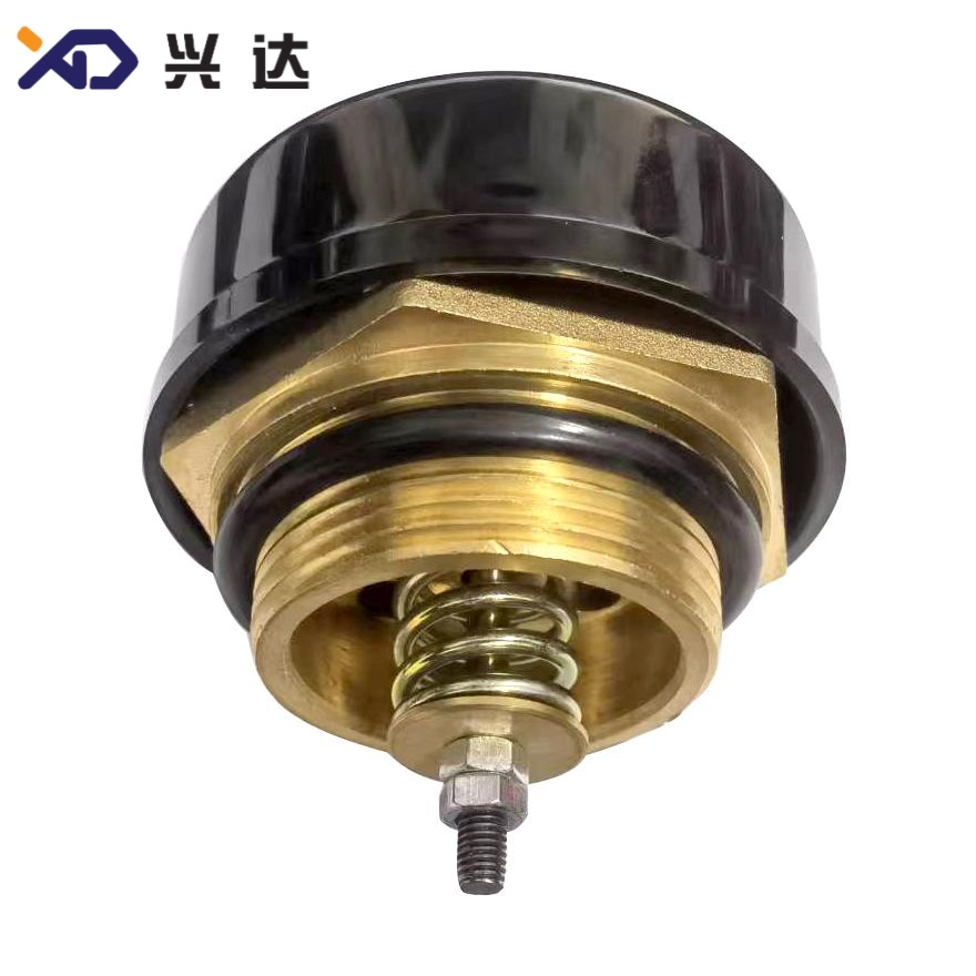
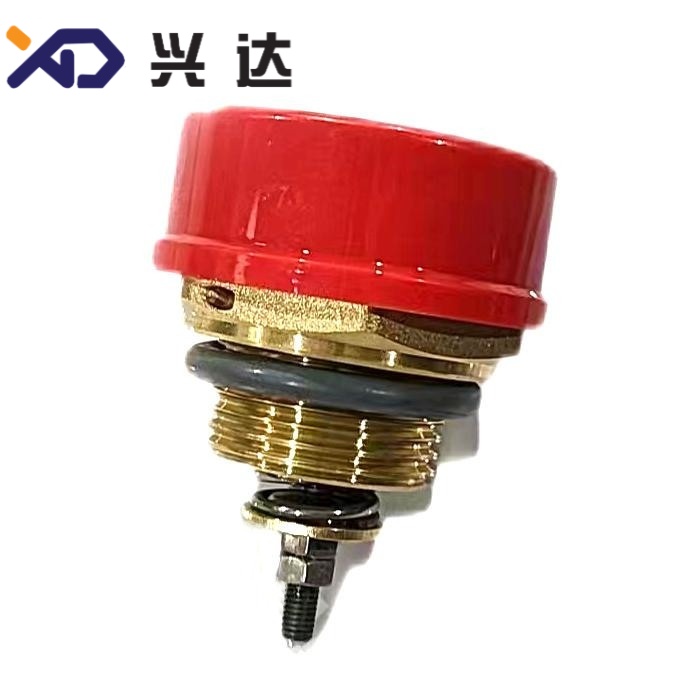
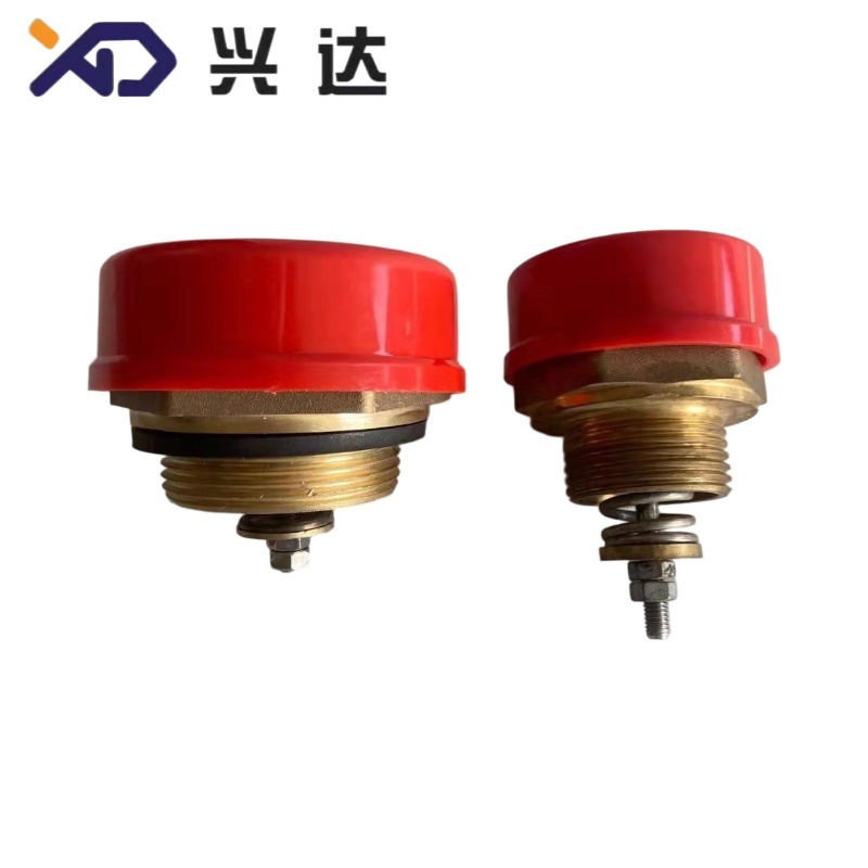
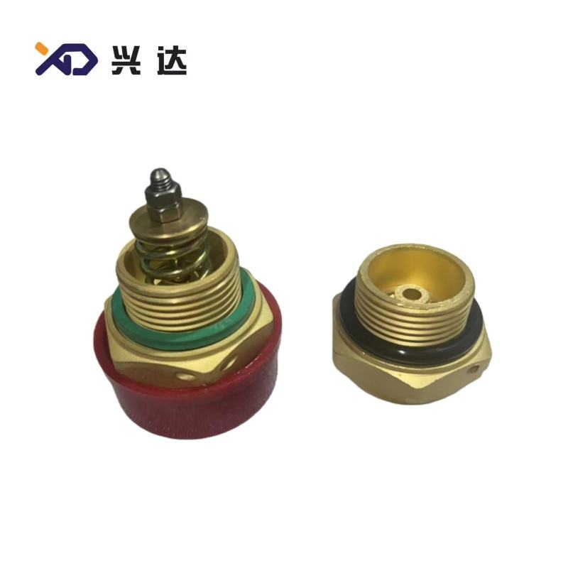
Pressure Relief Valve, Safety Pressure Relief Device for Oil‑Immersed Distribution Transformer
Pressure Relief Valve: Complete Technical Guide for Oil‑Immersed Transformer Safety Devices
Introduction
A pressure relief valve, also widely named pressure relief device (PRD), is a mandatory passive safety component fitted to oil‑immersed distribution and power transformers, on‑load tap‑changer tanks and oil‑filled reactors. Its core objective is to protect metallic transformer tanks against permanent deformation or catastrophic rupture when dangerous internal pressure surges take place during electrical faults such as internal short‑circuits, winding arcing or severe overheating.
When internal faults occur inside oil‑filled equipment, insulating mineral oil decomposes rapidly and generates large‑volume high‑pressure gas and oil vapour within milliseconds. The conservator and breather assembly cannot dissipate such fast‑rising pressure quickly enough, leaving the tank exposed to explosion risk. The pressure relief valve reacts almost instantly, venting a mixture of gas and hot transformer oil to atmosphere; once internal pressure falls back to safe operating levels, the unit automatically reseals without manual reset operation.
This industry‑oriented article delivers generic technical knowledge, performance tables, structural breakdown, application‑specific advantages, selection criteria, typical failure patterns as well as installation‑maintenance best‑practice guidance. The content is fully suitable for Google‑indexed industry blogs, technical directory pages and component knowledge libraries. No specific manufacturer, brand or commercial product recommendation is included throughout the whole document. Power‑system procurement engineers, transformer OEM technicians, field maintenance contractors and spare‑part buyers regularly search for pressure relief valve specifications, dimension guidance and troubleshooting references for tender projects and equipment‑repair workflows.
What is a Transformer Pressure Relief Valve
The transformer pressure relief valve is a spring‑loaded, resealable over‑pressure protection device, mounted onto the top cover or upper side‑wall of sealed oil‑filled transformer tanks. It replaces older‑generation non‑reusable rupture‑diaphragm explosion tubes, which could only perform one‑time pressure release and required full replacement after every activation event.
Standard pressure relief valve assemblies combine mechanical pressure‑sensing hardware plus optional electrical signal‑switch modules. When tank internal pressure exceeds the calibrated opening‑pressure threshold, the valve disc lifts quickly to release pressure. As tank pressure drops below the defined closing‑pressure value, compressed springs push the sealing disc back into its seat to restore tank tightness, blocking moisture and air ingress into transformer insulating oil. Many units integrate mechanical trip flags and micro‑switch contacts, sending remote alarm or trip‑command signals to SCADA and protection relay systems when pressure‑relief action is triggered.
Two major structural classifications exist across global power‑equipment markets: external‑spring type and internal‑spring type pressure relief valves. The external‑spring variant remains dominant for distribution‑class and medium‑power transformers, since its spring assembly stays outside the oil cavity and avoids direct contact with hot transformer oil, improving long‑term anti‑aging performanceGlobal Ene.... Internal‑spring constructions see limited deployment on special high‑voltage power‑transformer projects.
Core Structure of Pressure Relief Valve
Each complete pressure relief valve unit consists of these key functional assemblies:
- Mounting Flange & Sealing Gasket: Aluminium or cast‑metal flange provides mechanical connection against transformer tank openings. Composite rubber gaskets eliminate oil leakage and prevent outside humidity from entering the oil compartment. Uniform bolt‑torque control is critical for long‑term sealing reliability.
- Calibrated Spring Pack: Pre‑loaded reverse‑wound spring groups deliver counter‑force to hold the valve disc closed under normal‑pressure operating status. Spring stiffness directly defines the valve opening‑pressure setting. Dual‑spring configurations are common to balance fast‑response performance and stable re‑closing characteristics.
- Valve Disc & Diaphragm Sealing Assembly: The disc‑diaphragm set forms the main pressure‑sensitive sealing interface. When internal tank pressure overcomes spring pre‑load force, the disc lifts to open the discharge passage for gas‑oil mixture venting.
- Discharge Outlet Port: Outlet nozzle for venting over‑pressure gas and oil. Directional‑discharge variants guide ejected media towards designated oil‑collection containers instead of spraying freely across transformer surfaces.
- Indicator & Signal‑Switch Module: Visible mechanical trip flag shows whether the valve has been actuated during fault events. Built‑in micro‑switches supply normally‑open / normally‑closed electrical contacts for remote monitoring, alarm triggering or circuit‑breaker tripping logic.
General Technical Specifications of Pressure Relief Valve
The following table summarizes widely‑adopted industry‑general parameter ranges for transformer‑grade pressure relief valves. These reference values apply for specification review, tender‑document compilation and spare‑part‑replacement evaluation; actual project parameters shall match local grid‑utility standards and transformer‑design documentation.
| Parameter | Typical Industry‑Standard Range | Important Remarks |
|---|---|---|
| Rated Opening Pressure | 25 kPa, 35 kPa, 55 kPa, 70 kPa, 85 kPa | 55 kPa for 110 kV‑class transformers; 70 kPa widely used for 220 kV and above power‑transformer applicationsGlobal Ene... |
| Corresponding Closing Pressure | 13 kPa ~ 38 kPa | Closing pressure is always lower than opening pressure for reliable re‑sealing after pressure relief |
| Effective Oil‑Jet Caliber (Nominal Diameter) | 25 mm, 50 mm, 80 mm, 130 mm,170 mm | Larger caliber handles higher‑volume oil‑gas discharge; selected by transformer total oil volume |
| Applicable Equipment | Oil‑immersed distribution transformers, power transformers, OLTC tap‑changer tanks, oil‑filled reactors | Not suitable for dry‑type transformers |
| Ambient Operating Temperature | ‑40 °C ~ +55 °C | Tropical‑area enhanced versions support hot‑humid and coastal salt‑fog environments |
| Installation Requirement | Mainly vertical mounting; allowable small inclination ≤15° | Excessive tilt impairs disc‑seating performance and re‑sealing reliability |
| Electrical Switch Contact Rating | 5 A / 250 VAC typical | Single‑channel or dual‑channel signal‑contact configurations available |
| Mechanical Service Life | ≥500 actuation cycles per standard requirements | Qualification test target for repeated‑opening‑closing performance |
| Protection Grade | IP54 general type; enhanced IP65 for heavy‑pollution outdoor sites | Enclosure grade prevents dust, rain and salt‑mist intrusion into switch‑component cavities |
| Transformer Oil‑Volume Matching | ≤1500 L (25 mm‑50 mm caliber); 1500‑9000 L (80 mm); >9000 L (130 mm‑170 mm) | Multiple pressure‑relief‑valve units can be installed for very‑large‑capacity transformer tanks |
Primary Advantages of Transformer Pressure Relief Valve
Modern transformer‑protection systems favour pressure relief valves over older‑style rupture‑disc explosion tubes for multiple practical engineering benefits:
1. Automatic Re‑sealing & Reusable Performance
Unlike single‑use rupture‑diaphragm safety tubes, qualified pressure relief valves close automatically after pressure drops back to safe levels. After one fault‑triggered actuation, the device can stay in service without mandatory component replacement, provided no mechanical damage occurs. This feature shortens transformer recovery timelines and reduces spare‑part consumption for power‑grid operators.
2. Ultra‑Fast Response for Fault‑Pressure Mitigation
Well‑specified pressure relief valves complete opening action within several milliseconds when facing steep internal‑pressure spikes, offering effective protection against tank bulging or cracking during sudden arc‑fault incidents. The quick‑release characteristic makes it the last‑line physical safety barrier complementing Buchholz relay electrical‑protection schemes.
3. Integrated Visual & Remote‑Signal Alarm Function
Combined mechanical trip‑flag and electrical‑switch outputs deliver dual‑mode fault notification. Field technicians can directly observe the mechanical flag during on‑site inspections; meanwhile, switch‑contact signals transmit fault‑event information to remote control rooms. Operators can implement timely transformer de‑energization to avoid secondary‑damage expansion. Dual‑signal‑contact versions support redundant signal‑transmission for high‑reliability power‑station projects.
4. Strong Environmental Adaptability
Standard‑specification pressure relief valves tolerate broad‑range outdoor‑climate conditions. Special‑modified variants support tropical high‑humidity regions, coastal salt‑fog pollution zones and high‑altitude installation sites. Anti‑aging sealing‑material formulations resist degradation from long‑term transformer‑oil contact and outdoor ultraviolet exposure.
5. Flexible‑size Matching for Diverse Transformer Capacities
Multiple nozzle‑caliber options cover small‑distribution‑transformer up to large‑power‑transformer oil‑volume requirements. Design engineers can select single‑valve or multi‑valve redundant layouts according to tank‑volume and mechanical‑strength‑design parameters, adapting to distribution‑network, substation and industrial‑power‑supply‑transformer scenarios.
Key Selection Checklist for Pressure Relief Valve
Improper specification selection will lead to ineffective‑protection or false‑activation risks. While specifying or replacing pressure relief valves, engineers must verify these items step‑by‑step:
- Confirm the correct opening‑pressure setting: The opening pressure value must align with the transformer tank mechanical‑strength design limit. It cannot be set excessively high (delayed relief action) or too low (frequent false tripping under normal thermal‑expansion pressure fluctuation).
- Match nozzle caliber against transformer total oil‑filling volume. Oversmall nozzle cannot release pressure rapidly enough under severe‑fault conditions; over‑large‑caliber valves increase procurement cost without extra practical benefits.
- Verify flange‑mounting dimensions: flange outer diameter, bolt‑hole‑circle diameter, bolt‑hole quantity and gasket‑sealing‑surface geometry. Voltage‑capacity parameters alone cannot guarantee mechanical fit during replacement‑part procurement.
- Confirm signal‑switch configuration requirements: single‑channel / dual‑channel contacts, contact‑capacity rating, normally‑open / normally‑closed contact logic according to substation‑protection‑system design.
- Evaluate site‑environment conditions: ambient‑temperature scope, coastal salt‑fog pollution, installation altitude, whether directional‑oil‑discharge outlet‑structure is required.
- Check installation‑angle constraint; prioritize vertical mounting. If inclined‑mounting is unavoidable, confirm valve‑model allows non‑vertical installation.
- Cross‑reference local‑utility acceptance‑test‑standard requirements for tender‑project‑procurement.
Common Failure Modes of Pressure Relief Valve
Understanding typical failure‑modes helps maintenance teams implement predictive inspection workflows and avoid hidden safety risks for transformer assets.
1. Leakage at Flange‑Gasket Joint
Oil seepage from the mounting‑flange gasket area represents one of the most‑frequently‑observed defects. Root causes include aging rubber gaskets, uneven bolt‑tightening torque, deformed flange surfaces, or foreign‑particle residues trapped between sealing mating faces. Continuous minor‑leakage allows moisture to penetrate into transformer‑tank interiors and degrades insulating‑oil dielectric‑performance.
2. Valve Disc Sticking, Failing to Open During Overpressure
Mechanical jamming stops the valve disc from lifting even when internal‑tank pressure reaches the set opening‑pressure threshold. Contributing factors include carbon‑sediment accumulation, oil‑sludge contamination, spring‑corrosion deformation or transportation‑induced mechanical‑component distortion. This failure mode is extremely dangerous, as the transformer loses critical over‑pressure‑release protection and faces tank‑rupture hazard during internal faults.
3. Poor Re‑sealing Performance After Actuation
After pressure‑relief‑valve triggering, the disc cannot achieve complete sealing when pressure drops below closing‑pressure set‑value. Oil‑sludge particles stuck on sealing‑seat surfaces, diaphragm‑disc permanent deformation or spring‑fatigue loss of pre‑load force are major causes. Consequences include sustained oil leakage and continuous air‑moisture ingress into transformer tanks.
4. False‑tripping (Unintended Actuation Under Normal Operation)
The valve opens without severe internal‑transformer faults. Root causes include incorrect‑low opening‑pressure calibration, mechanical vibration from nearby equipment, thermal‑expansion‑generated pressure spikes inside hermetically‑sealed small‑capacity transformers, or external‑mechanical impact damage. Frequent false‑tripping triggers unnecessary remote‑alarm events and disturbs grid‑operation stability.
5. Signal‑Switch Failure
The mechanical‑trip flag shows valve‑activation status, but electrical‑switch contacts cannot output correct alarm‑trip‑signals. Causes include switch‑component aging, wiring‑loosening, contact‑surface oxidation or mechanical‑linkage‑part displacement. Operators lose remote‑monitoring capability although mechanical‑pressure‑protection‑function remains intact.
Installation & Maintenance Best‑Practices
Correct installation and periodic inspection‑maintenance extend pressure‑relief‑valve service‑life and reduce transformer‑safety‑incident probability.
Installation Guidelines
- Complete visual inspection before installation: check flange‑body deformation, diaphragm‑disc damage, spring‑corrosion, gasket‑aging, and signal‑switch‑module integrity. Discard any visibly‑damaged units.
- Remove transportation‑protective safety cap before transformer commissioning; keep protective‑cap on only during transit and storage.
- Clean transformer‑tank‑mounting‑face and valve‑flange sealing‑surface thoroughly; remove old‑gasket‑residues, metal‑burrs and debris. Apply brand‑new matched‑specification sealing gaskets; re‑using old gaskets is prohibited.
- Tighten flange bolts following cross‑symmetrical‑torque‑sequence. Over‑torque risks flange‑cracking; under‑torque results in oil‑leakage defects.
- Maintain vertical installation orientation as much as possible. If inclined‑mounting is required, strictly follow the equipment‑model‑allowed inclination‑angle limit.
- Complete manual‑simulation test for mechanical‑trip‑flag and electrical‑switch‑signal‑output before transformer energization, verifying alarm‑trip‑logic works as‑designed.
- When directional‑discharge piping is connected, avoid applying heavy mechanical cantilever‑load onto valve‑outlet ports.
Routine‑Maintenance Recommendations
- Monthly visual‑inspection tasks: check flange‑gasket positions for oil‑leakage traces; observe mechanical‑trip‑flag status; inspect enclosure‑integrity for outdoor‑exposed units. If the trip‑flag shows actuation occurrence, lock‑out‑tag‑out the transformer and execute full‑fault‑diagnosis before resetting the flag and re‑energizing equipment.
- Annual maintenance work: simulate‑actuation test for electrical‑signal‑switch contacts; inspect wiring‑terminal‑connection tightness.
- Major transformer overhaul cycle (every 4‑5 years): replace mounting‑flange gaskets; disassemble‑inspect disc‑diaphragm‑sealing‑surface, check‑spring‑corrosion‑fatigue condition; perform pressure‑test‑verification for opening‑pressure and re‑sealing‑performance.
- Store spare pressure‑relief‑valve stock inside dry‑covered warehouses; avoid long‑term outdoor‑stacking exposure to rain and salt‑mist.
Conclusion
Pressure relief valves occupy an irreplaceable safety‑protection position within oil‑immersed transformer‑systems. As the final physical‑defense barrier preventing tank rupture caused by internal‑fault‑pressure surges, its reliable performance directly determines transformer‑asset safety and power‑grid‑operating‑stability.
During component‑specification and replacement‑procurement phases, technical teams should focus not merely on opening‑pressure parameters, but also nozzle‑caliber‑oil‑volume‑matching, flange‑mounting‑dimensional‑compatibility, site‑environmental‑conditions, signal‑contact‑configuration and installation‑process‑standardization. Recognizing common‑failure‑modes and executing standardized installation‑maintenance workflows effectively reduce avoidable transformer‑outage and safety‑accident risks.
With continuous global‑power‑grid‑infrastructure‑expansion, proper specification, quality‑control and field‑application of pressure relief valves remain critical technical topics for transformer‑design‑engineers, OEM‑procurement‑teams and power‑utility‑maintenance‑departments.
Categories
Contact Us
Contact: Tianjin Delda Trading Co., Ltd
WhatsApp: +86 13662056855
Tel:
E-mail: solomon20210701@tjxddq.com
Add: Unit‑101, Workshop 3, Bozhong Automobile Industrial Park, No.5 Xianghui Road, Intersection of Xianghui Road and Gaoying Road, Beizhakou Town, Jinnan District, Tianjin, China