Tap changer
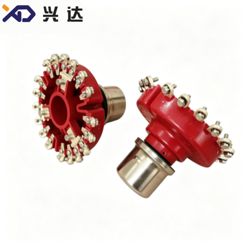
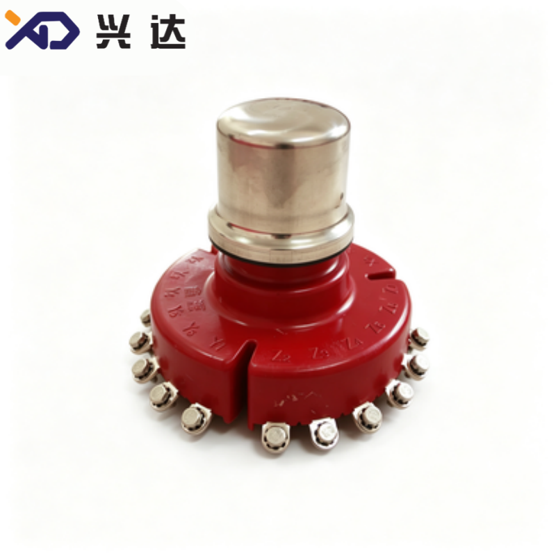
No Excitation Disk Type Tap Changer for Oil‑Immersed Distribution Transformers
No‑Excitation Disk‑Type Tap Changer
Overview
Power distribution transformers are the core equipment for voltage conversion in power grids. Fluctuations of grid input voltage will directly affect the power quality of end‑user facilities. Tap changers are essential components designed to adjust transformer turn‑ratio for stabilizing output voltage. Among multiple tap‑regulating solutions, the No‑Excitation Disk‑Type Tap Changer, also widely known as off‑circuit disk‑type tap changer, is a mainstream voltage‑adjusting device specially applied for oil‑immersed distribution transformers.
Different from on‑load tap‑changers that perform tap shifting under live operating status, the no‑excitation disk‑type tap changer must complete tap position switching after the transformer is fully de‑energized. It is extensively deployed in 10kV and 35kV class distribution transformers for urban power grids, rural power networks, industrial parks and new‑energy auxiliary transformation equipment. With compact disk‑shaped layout, simple mechanical operation and cost‑effective performance, this type of tap changer occupies a large market share in medium‑voltage distribution transformer projects globally.
Improper tap‑changer selection or mechanical defect may lead to abnormal voltage output, excessive contact resistance, local overheating and even transformer internal faults. Therefore, system designers and transformer manufacturers need to fully understand working principles, performance indexes, selection rules and installation requirements of no‑excitation disk‑type tap changers during component specification.
What is No‑Excitation Disk‑Type Tap Changer
The no‑excitation disk‑type tap changer is an off‑circuit voltage‑regulation component for oil‑immersed transformers. Its disk‑shaped main body can be mounted on transformer tank cover or tank wall. All tap shifting operations must be carried out when the transformer is completely powered off and de‑excited.
The device consists of moving contact assembly, static contact groups, insulating support structure, operating shaft and sealing components. Inside oil‑filled transformers, the contacts are immersed in insulating transformer oil. Operators rotate the upper operating hand‑piece to drive internal disk‑shaped moving contacts, completing switching among different tap positions to change transformer winding turns ratio, so as to realize output voltage correction.
Mainstream industry models cover rated current levels of 63A, 125A, 250A and 400A. The common rated voltage classes include 10kV and 35kV. Two typical voltage regulation ranges are ±5% and ±2×2.5%. Most products adopt 3‑phase integrated structure for three‑phase oil‑immersed transformers, adapting to 50Hz and 60Hz power‑system frequency requirements for global markets.
Core Benefits of No‑Excitation Disk‑Type Tap Changer
Compact Disk‑Shaped Mechanical StructureThe disk‑type integrated layout saves internal space inside transformer tanks. It can be directly installed on tank cover or side wall, bringing high layout flexibility for transformer structural design. Compared with split tap‑changing structures, this design reduces component quantity and simplifies assembly workflow.
Accurate Positioning & Clear Operating FeedbackPrecise mechanical positioning mechanism ensures that moving contacts lock firmly at each tap position. Operators can obtain obvious hand‑feel feedback during rotation, effectively avoiding mis‑position caused by incomplete switching. Reliable positioning prevents poor contact risks under long‑term transformer operation.
Low Contact ResistanceHigh‑quality contact materials are adopted to keep stable low contact resistance. It avoids local overheating when rated current passes through contact points, delivering stable thermal performance under continuous operating conditions.
Excellent Sealing PerformanceMatching sealing structures between operating shaft and transformer tank prevent transformer‑oil leakage. It keeps insulating oil clean inside the tank and stops outside moisture and pollutants from invading transformer interior.
Cost‑Effective & Easy‑to‑MaintainCompared with complex on‑load tap‑changer units, no‑excitation disk‑type tap changers feature lower procurement cost and fewer vulnerable parts. Routine maintenance workload is minimal, which makes it ideal for mass‑produced distribution transformers in general‑purpose power‑distribution scenarios.
Wide Compatibility for Standard TransformersMultiple standard series cover mainstream current, voltage and voltage‑regulation‑range parameters. Standard installation dimensions fit most conventional oil‑immersed distribution transformer designs. Custom dimensional solutions are available for special tank‑structure requirements.
General Technical Specifications
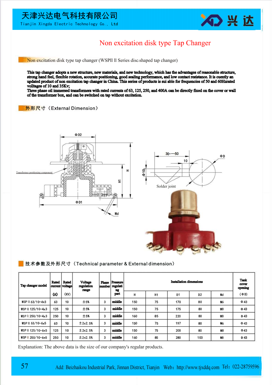
Industry‑general typical parameters for No‑Excitation Disk‑Type Tap Changer
| Tap Changer Model | Rated Current(A) | Rated Voltage(kV) | Voltage Regulation Range | Phase Number | Pressure Regulating Part |
|---|---|---|---|---|---|
| WSPⅡ 63/10‑4×3 | 63 | 10 | ±5% | 3 | middle |
| WSPⅡ 125/10‑4×3 | 125 | 10 | ±5% | 3 | middle |
| WSPⅡ 250/10‑4×3 | 250 | 10 | ±5% | 3 | middle |
| WSPⅡ 63/10‑6×5 | 63 | 10 | ±2×2.5% | 3 | middle |
| WSPⅡ 125/10‑6×5 | 125 | 10 | ±2×2.5% | 3 | middle |
| WSPⅡ 250/10‑6×5 | 250 | 10 | ±2×2.5% | 3 | middle |
Installation Dimension Reference
All dimensions in millimeter (mm)
| Tap Changer Model | H | H1 | D1 | D2 | Md | Tank Cover Opening ΦD |
|---|---|---|---|---|---|---|
| WSPⅡ 63/10‑4×3 | 150 | 75 | 170 | 80 | M6 | Φ43 |
| WSPⅡ 125/10‑4×3 | 150 | 75 | 175 | 80 | M8 | Φ43 |
| WSPⅡ 250/10‑4×3 | 160 | 85 | 220 | 80 | M8 | Φ43 |
| WSPⅡ 63/10‑6×5 | 150 | 75 | 197 | 80 | M6 | Φ43 |
| WSPⅡ 125/10‑6×5 | 150 | 75 | 200 | 80 | M8 | Φ43 |
| WSPⅡ 250/10‑6×5 | 160 | 85 | 280 | 103 | M8 | Φ43 |
Main Application Scenarios
10kV Urban & Rural Distribution TransformersThis is the largest‑volume application. No‑excitation disk‑type tap changers are widely fitted on oil‑immersed distribution transformers for town and countryside power grids, compensating voltage deviation caused by long‑distance power transmission. Tap adjustment is completed during regular power‑cut maintenance windows.
Industrial Plant Distribution TransformersFactories, manufacturing parks and mining facilities adopt distribution transformers equipped with disk‑type no‑excitation tap changers. Users adjust tap positions according to actual incoming‑grid voltage conditions before putting transformers into service.
Auxiliary Transformers for Photovoltaic and Wind‑Power StationsNew‑energy power stations use large quantities of distribution‑class transformers. For scenarios allowing power‑off tap adjustment, no‑excitation disk‑type tap changers become an economical alternative to high‑cost on‑load tap‑changing equipment.
Commercial Building Power‑Supply TransformersShopping malls, office complexes and public infrastructure distribution transformers also adopt this off‑circuit tap‑changing solution for static voltage regulation.
Key Selection Guidelines
When specifying no‑excitation disk‑type tap changers, engineering teams need to confirm multiple critical parameters:
Rated Current: Must be higher than the maximum continuous operating current of transformer winding. Common options: 63A,125A,250A,400A.
Rated Voltage: Match transformer voltage class, mainly 10kV and 35kV for mainstream series.
Voltage‑Regulation Range: Choose between ±5% or ±2×2.5% according to local grid‑voltage fluctuation level.
Phase configuration: 3‑phase integrated structure is standard for most three‑phase transformers.
Installation dimensions: Verify H, H1, D1, D2, thread specification Md and tank‑cover opening diameter ΦD to match transformer tank mechanical design.
System frequency: Confirm compatibility for 50Hz or 60Hz power network requirements for export‑oriented transformer projects.
Working environment: For high‑altitude, high‑humidity or heavily polluted sites, insulation performance shall take altitude correction and environmental degradation factors into consideration.
Installation & Operating Best Practices
Tap‑changing operation must be performed after the transformer is fully de‑energized, locked‑out and tagged. Never carry out tap switching under energized status, which will result in serious arc damage.
Check tap‑changer appearance before assembly: confirm insulating parts without cracks, contacts without deformation, operating shaft rotates smoothly with clear positioning click‑feedback.
Install gaskets properly between tap‑changer base and transformer tank cover. Tighten mounting bolts evenly to prevent oil leakage.
After installation and before oil filling, manually rotate the operating shaft for full‑range cycles to verify smooth switching and accurate positioning for every tap position.
After transformer oil filling, keep sufficient standing time for air bubble elimination. Measure DC resistance of each tap position to verify good contact status.
In field operation, mark current tap position clearly. Record tap‑position data in equipment files. All tap‑position changes must be executed under power‑off conditions.
Typical Faults and Countermeasures
Poor contact & excessive DC resistanceCauses: incomplete switching position, contact surface oxidation, mechanical positioning failure. Solution: Ensure full rotation to locked position during tap adjustment; check contact condition during transformer overhaul; select tap‑changer with reliable positioning mechanism.
Oil leakage at mounting flange or operating shaftCauses: gasket aging, uneven bolt tightening, component dimensional mismatch. Solution: Use qualified sealing gaskets; apply cross‑sequence uniform torque for bolt fastening; verify dimension matching before installation.
Positioning failure and unclear operating hand‑feelCauses: Internal mechanical part wear, assembly deviation. Solution: Avoid violent rotation during operation; inspect mechanical structures during routine maintenance.
Insulation defectsCauses: Insulating component damage, moisture ingress, residual metal debris inside transformer oil chamber. Solution: Protect tap‑changer from impact in transportation and assembly; keep internal chamber clean during transformer manufacturing.
Conclusion
No‑Excitation Disk‑Type Tap Changer remains a fundamental voltage‑regulation component for global medium‑voltage oil‑immersed distribution transformers. Benefiting from compact disk‑shaped structure, reliable mechanical positioning, low contact resistance and outstanding cost performance, it is widely adopted for power‑grid distribution, industrial facilities and new‑energy auxiliary transformation equipment.
Users must keep in mind its core operating constraint: all tap‑position switching can only be completed under transformer de‑excitation status. Correct parameter selection, standardized installation and periodic inspection are essential prerequisites for long‑term safe operation. As global distribution‑transformer market continues to develop, no‑excitation disk‑type tap changers will sustain irreplaceable application value for general‑purpose off‑circuit voltage‑regulation scenarios.
Categories
Contact Us
Contact: Tianjin Delda Trading Co., Ltd
WhatsApp: +86 13662056855
Tel:
E-mail: solomon20210701@tjxddq.com
Add: Unit‑101, Workshop 3, Bozhong Automobile Industrial Park, No.5 Xianghui Road, Intersection of Xianghui Road and Gaoying Road, Beizhakou Town, Jinnan District, Tianjin, China