Transformer bushing
OIP Bushing: A Complete Technical Guide for High‑Voltage Transformer Applications
OIP Bushing: A Complete Technical Guide for High‑Voltage Transformer Applications
Introduction
OIP bushing (Oil‑Impregnated Paper bushing) is a fundamental high‑voltage insulating component built for power transformers, instrument transformers and other high‑voltage electrical apparatus in transmission and distribution power grids. As a critical interface between the energized internal winding and grounded transformer tank, the OIP bushing conducts load current while providing reliable electrical insulation. Manufactured in compliance with IEC 601337‑2017 standards, OIP bushing has become a widely‑accepted solution for medium‑voltage, high‑voltage and extra‑high‑voltage power infrastructure projects around the world.
This article covers OIP bushing core definitions, internal construction, key performance benefits, standard technical ratings, real‑world applications, selection criteria, maintenance best practices, and comparison with alternative bushing technologies. Optimized for search engine indexing, this resource is suitable for technical blogs, industry knowledge directories and electrical engineering reference pages, with all data based on generic international industry standards.
What Is an OIP Bushing?
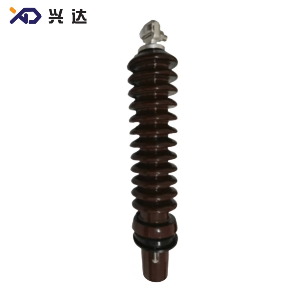
An OIP bushing is a current‑carrying insulated assembly whose main dielectric system is constructed using multi‑layer cellulose kraft paper that is vacuum‑dried and fully saturated with degassed transformer mineral oil. The oil‑paper composite insulation system eliminates air voids that would trigger partial discharge, ensuring stable dielectric strength under continuous high‑voltage stress.
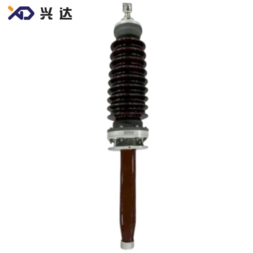
A standard OIP bushing consists of several core parts: central metallic conductor for carrying operating current, oil‑impregnated paper insulation core, mounting flange for installation on transformer tank, external porcelain or composite sheds for outdoor insulation, oil conservator for thermal expansion of insulating oil, test tap for condition measurement, and multi‑component sealing systems to prevent oil leakage.
During normal operation, the central conductor passes full rated load current out through the wall of the earthed transformer tank. The oil‑impregnated paper core separates live high‑voltage potential from grounded metal structures. The mineral oil inside the OIP bushing serves two primary purposes: electrical insulation and heat dissipation. Heat generated by conductor losses flows into the oil and dissipates outward, avoiding dangerous hot‑spot temperatures that degrade insulation lifespan.
Designed per IEC 601337‑2017, OIP bushing must withstand power‑frequency operating voltage, lightning impulse surges and switching over‑voltages that occur within utility power networks. Decades of field operation confirm OIP bushing as a mature, proven high‑voltage component for substations, power plants and grid renovation projects.
Main Advantages of OIP Bushing
Electrical designers frequently specify OIP bushing for transformer projects due to multiple practical, field‑proven technical strengths.
First, OIP bushing delivers excellent dielectric stability under long‑term high‑voltage stress. Proper vacuum processing and full oil impregnation minimize partial discharge activity, one of the leading causes of premature bushing failure. Its insulation performance remains consistent across wide temperature fluctuations caused by cyclic transformer loading.
Second, OIP bushing offers superior thermal performance for high‑current service. Liquid mineral oil inside the bushing creates efficient heat transfer paths. This characteristic makes OIP bushing well suited for large power transformers that regularly run at full‑load or temporary overload conditions in major transmission substations and power generation facilities.
Third, OIP bushing technology is fully mature with well‑established manufacturing, testing and maintenance workflows. Oil‑paper bushing technology has been deployed globally for many decades. Utility engineers and field maintenance teams have accumulated extensive experience for installation, diagnostics and troubleshooting of OIP bushing hardware. Standard type‑test protocols defined by IEC 601337‑2017 unify performance requirements across global markets.
Fourth, OIP bushing supports flexible scaling for broad voltage and current ranges. Customized OIP bushing designs cover medium‑voltage classes all the way through extra‑high‑voltage transmission grades, and can support very high continuous rated current for large‑capacity main transformers.
Fifth, OIP bushing enjoys good material compatibility with standard transformer mineral oil. The insulating oil sealed inside the OIP bushing matches the oil inside the main transformer tank. In case of minor seal seepage, cross‑contamination risks between bushing oil and tank oil are minimal.
While OIP bushing brings major benefits, it also has inherent characteristics users must consider. Since insulation depends on liquid mineral oil, reliable sealing and periodic oil‑based diagnostic testing are required throughout its service life. Oil leakage, moisture ingress or oil degradation will degrade bushing performance.
IEC 601337‑2017 Standard Rating Table for OIP Bushing
The table below reproduces core standard rating parameters for common OIP bushing voltage classes following IEC 601337‑2017 specifications.
| Standard | Unit | IEC 601337‑2017 | IEC 601337‑2017 | IEC 601337‑2017 | IEC 601337‑2017 | IEC 601337‑2017 |
|---|---|---|---|---|---|---|
| Highest voltage for equipment Um | kV | 72.5 | 100 | 123 | 145 | 170 |
| Rated frequency | Hz | 50/60 | 50/60 | 50/60 | 50/60 | 50/60 |
| Lightning impulse (BIL) | kV | 325 | 450 | 550 | 650 | 750 |
| Maximum Rated Current | A | 3150 | 3150 | 3150 | 3150 | 3150 |
Key parameter explanations:
Highest voltage for equipment Um: Defines the maximum continuous system operating voltage the OIP bushing can withstand safely. Um must be equal to or higher than the maximum system operating voltage at project site.
Rated frequency: Supports both 50 Hz and 60 Hz global power grid systems.
Lightning impulse (BIL): Basic Impulse Level represents lightning surge withstand capability, a critical insulation design index for outdoor high‑voltage equipment. Regions with frequent lightning activity require higher BIL ratings.
Maximum Rated Current: The maximum continuous load current the central conductor can carry without exceeding permitted temperature‑rise limits.
Beyond these tabulated values, OIP bushing must complete full type‑tests according to IEC 601337‑2017. Mandatory test items include power‑frequency voltage withstand test, partial discharge measurement, temperature‑rise test, mechanical strength test and sealing tightness verification. These validation tests guarantee safe and reliable performance under real‑world grid operating conditions.
Typical Applications of OIP Bushing
OIP bushing is widely used across power generation, transmission and distribution segments.
The largest application is high‑voltage bushings for main power transformers inside AC transmission substations. Step‑up transformers for thermal power plants, hydroelectric stations and renewable energy power facilities use OIP bushing to connect transformer internal windings to overhead transmission lines.
Generator step‑up transformers represent another major use case. These units operate with very high continuous current values, and the outstanding thermal performance of OIP bushing fits these demanding working conditions. OIP bushing can also be fitted to certain high‑voltage instrument transformers including current transformers and voltage transformers within high‑voltage switchgear yards.
Grid modernization and refurbishment projects frequently select OIP bushing as replacement spare parts. When old existing bushings suffer oil leakage, insulation ageing or mechanical damage, site crews install new standard‑compliant OIP bushing to restore full transformer operational safety.
OIP bushing can be deployed for both indoor and outdoor installation environments. For coastal sites with salt fog or industrial locations with heavy airborne pollution, OIP bushing should be configured with anti‑pollution extended shed profiles to prevent external surface flash‑over faults under contaminated atmospheric conditions.
Critical Factors for OIP Bushing Selection
Correct specification is essential to achieve long‑term OIP bushing service life and reduce failure risks.
Highest voltage for equipment Um: The selected OIP bushing Um rating must match or exceed the maximum continuous system operating voltage on‑site.
Rated continuous current: Calculate required current rating based on transformer nominal current plus sufficient overload safety margin to avoid conductor overheating during seasonal peak‑load periods.
BIL lightning impulse rating: Adjust BIL value according to local lightning exposure levels. High‑lightning zones require higher impulse withstand ratings.
Environmental conditions: Ambient temperature, installation altitude, pollution severity class and humidity determine required external shed design and insulation creepage distance.
Mechanical interface compatibility: Mounting flange dimensions, hole pattern, installation height and oil chamber connections must match reserved openings on the transformer tank.
Standard compliance: Verify full compliance with IEC 601337‑2017 and availability of valid type‑test documentation before procurement.
During specification work, engineers must distinguish OIP bushing from RIP bushing. RIP bushing uses resin‑impregnated solid paper without liquid oil filling. While RIP bushing reduces oil‑leakage risks, it has practical limits on maximum continuous current and thermal overload tolerance. For high‑current large‑capacity transformers, OIP bushing remains a preferred industry choice. The final selection should always be application‑specific.
Operation and Preventive Maintenance for OIP Bushing
Regular inspection and condition‑based maintenance extend OIP bushing operating life and help avoid unplanned power outages.
Routine visual inspection is the first basic maintenance step. Field technicians check external insulator sheds for cracks, surface contamination, tracking marks and oil seepage. Any oil leakage at flange joints or conservator requires immediate corrective action. Loss of insulating oil will lower dielectric performance and may initiate dangerous internal partial discharge.
Dissolved Gas Analysis (DGA) of bushing oil is one of the most powerful diagnostic tools. Periodic oil sampling and laboratory gas testing detect early‑stage insulation degradation, thermal faults or partial discharge activity inside the oil‑paper system. Maintenance teams can schedule planned replacement before catastrophic bushing failure takes place.
Capacitance and dissipation factor (tan delta) measurement is another key offline test. Obvious drift of capacitance or tan‑delta readings signals moisture ingress or progressive ageing of paper insulation. Many modern OIP bushing units are equipped with test taps to support partial discharge monitoring.
For spare‑part storage, OIP bushing must be kept vertically. Long‑term horizontal storage may deform the internal paper core and damage rubber sealing gaskets. Oil level should stay within marked reference range, and storage space needs to remain dry with stable temperature. Before installation, vacuum treatment is needed to remove residual moisture and trapped air.
For heavily polluted sites, regular external insulator washing reduces surface leakage current and prevents flash‑over accidents. Recommended maintenance intervals are determined by site pollution severity, bushing voltage class and local utility operating experience.
OIP Bushing vs RIP Bushing: Technology Comparison
OIP bushing and RIP bushing are two mainstream high‑voltage bushing solutions for transformer projects.
OIP bushing uses oil‑impregnated paper dielectric with sealed mineral oil. It delivers excellent heat dissipation and high‑current capacity, with decades of proven field history. The downside is that it needs ongoing oil‑system inspection, seal checks and periodic DGA testing.
RIP bushing adopts resin‑impregnated paper with solid epoxy dielectric material, containing no liquid oil. Oil‑free construction simplifies maintenance and eliminates oil‑spill hazards. However, RIP bushing has constraints on maximum continuous rated current and overload thermal endurance.
There is no universal better solution. Engineers compare system voltage, operating current, site maintenance resources and environmental conditions to make proper technology selection for each individual project.
Conclusion
OIP bushing remains a reliable, widely deployed high‑voltage insulating component for power transformers in global energy networks. Built around oil‑paper composite dielectric and built to IEC 601337‑2017 international standards, OIP bushing combines stable insulation performance and strong current‑carrying capacity for power generation plants, transmission substations and grid upgrade projects.
Appropriate technical specification, professional installation and regular preventive maintenance are critical to maximize OIP bushing service life and guarantee grid safety. Deep understanding of OIP bushing parameters, application boundaries and condition‑monitoring techniques helps electrical engineers and procurement specialists make well‑informed technical decisions during transformer design and component sourcing. As worldwide power infrastructure continues expanding, OIP bushing will keep playing an irreplaceable role in high‑voltage transformer systems.
Categories
Contact Us
Contact: Tianjin Delda Trading Co., Ltd
WhatsApp: +86 13662056855
Tel:
E-mail: solomon20210701@tjxddq.com
Add: Unit‑101, Workshop 3, Bozhong Automobile Industrial Park, No.5 Xianghui Road, Intersection of Xianghui Road and Gaoying Road, Beizhakou Town, Jinnan District, Tianjin, China