Transformer bushing
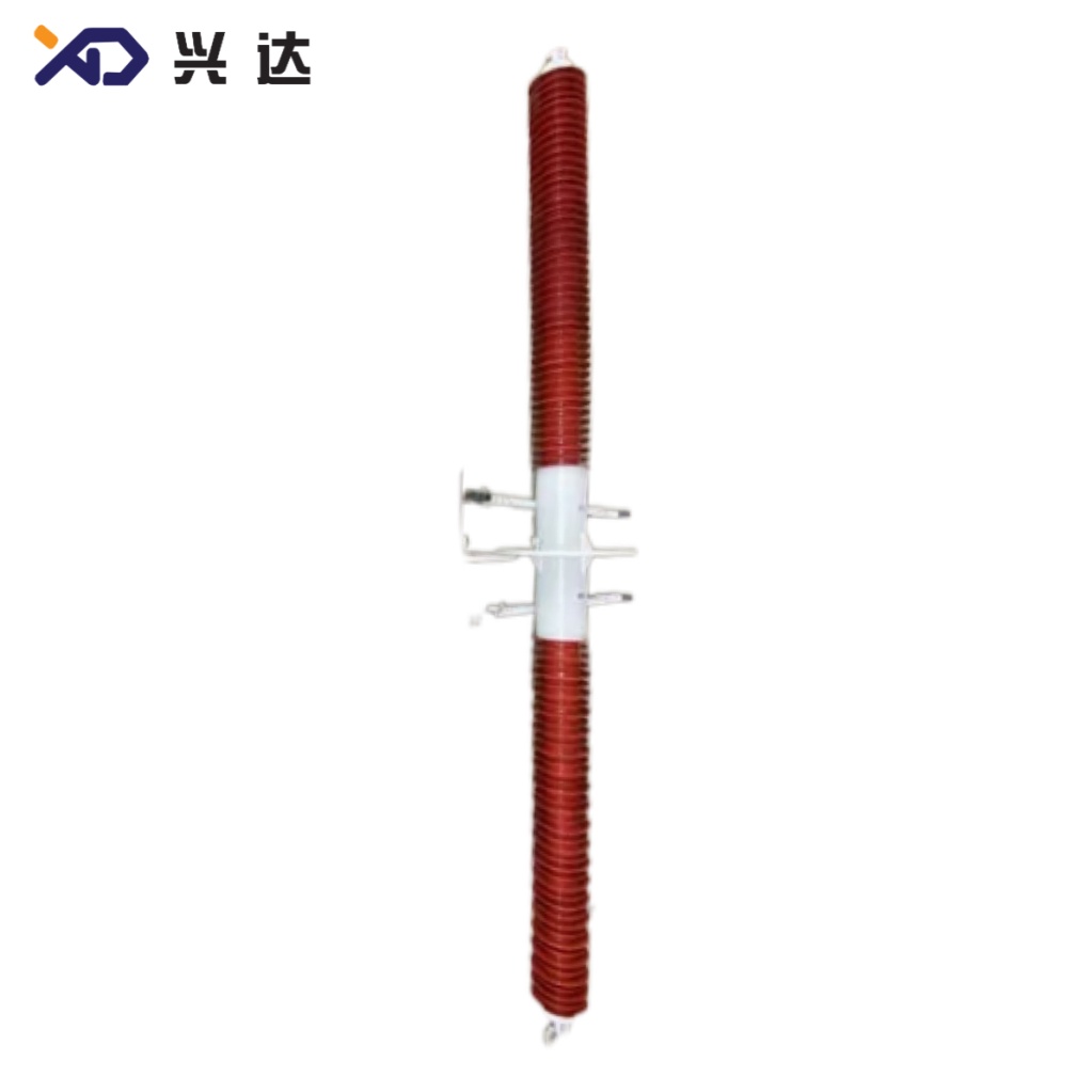
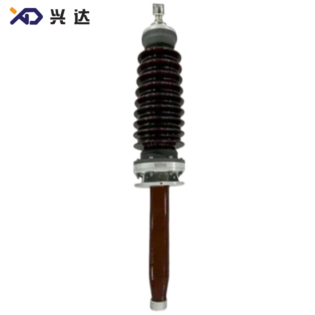
OIP Bushing Complete Technical Guide
OIP Bushing Complete Technical Guide
Introduction to OIP Bushing
Oil‑Impregnated Paper (OIP) bushing is one of the most widely adopted condenser‑type high‑voltage bushings for power transformers and substations across global power grids. As a core insulating component, OIP bushing establishes insulated conductive passage when high‑voltage conductors pass through grounded tank walls of power transformers, reactors and switchgear equipment. It separates live high‑potential parts from grounded metal structures while carrying continuous rated operating current under normal and transient grid conditions.
OIP bushing adopts oil‑impregnated kraft paper as its main dielectric material. Multi‑layer conductive foil electrodes are interleaved inside paper insulation to form a capacitive core structure. This capacitive grading design uniformly distributes electric field along both axial and radial directions of the bushing, effectively eliminating local electric field concentration, suppressing partial discharge risk and improving overall insulation reliability under long‑term AC operation.
Compliant with IEC 601337‑2017 international standard, modern OIP bushings cover medium‑voltage up to high‑voltage classes for transmission power projects. Engineers and procurement teams reference standard rating tables to match proper Um (highest voltage for equipment), BIL lightning impulse withstand level, rated current and frequency parameters for specific transformer and substation projects. Compared with RIP (Resin‑Impregnated Paper) bushing, OIP bushing features mature manufacturing process, stable long‑time dielectric performance and competitive total cost for most conventional power transmission applications.
Core Working Principle of OIP Condenser‑Type Bushing
The capacitive core is the heart component of OIP bushing. Wound high‑grade insulating paper together with thin metallic grading foils forms concentric capacitive layers. Each foil segment adjusts capacitance value to redistribute electric field stress evenly across the whole insulation body. Without capacitive grading, heavy electric field distortion would appear at flange and conductor zones, triggering partial discharge, insulation aging and premature bushing failure.
After winding, the paper core goes through strict vacuum drying and mineral oil impregnation procedures. Vacuum processing removes residual moisture and air bubbles trapped inside paper layers. Full oil impregnation fills every tiny gap inside cellulose paper. Moisture and air are fatal enemies for high‑voltage paper insulation. Even tiny air cavities will initiate partial discharge under operating voltage, gradually erode paper fibers and finally lead to insulation breakdown.
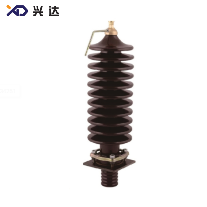
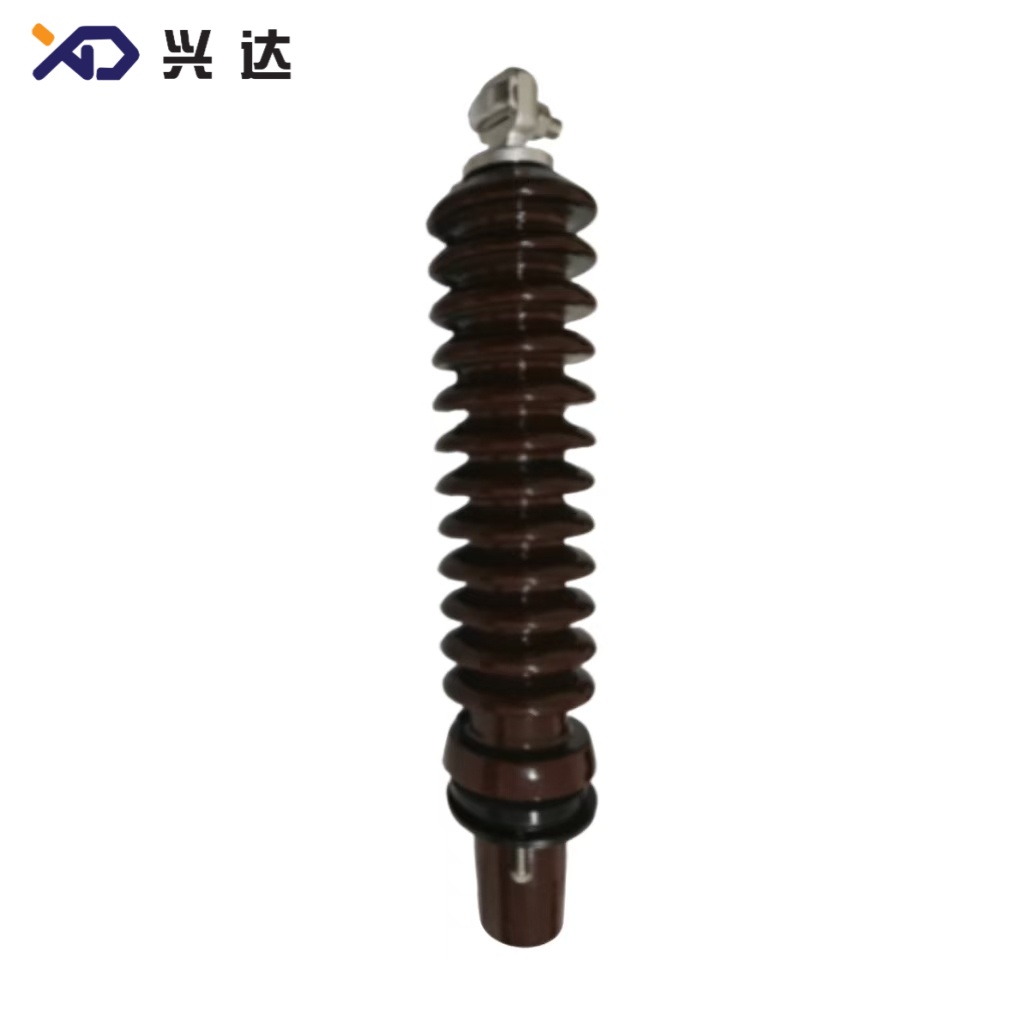
The complete OIP bushing assembly consists of central current‑carrying conductor, OIP capacitive core, upper porcelain or composite shed insulator, lower oil‑immersed porcelain/composite insulator, mounting flange, oil reservoir, voltage tap and test tap terminals. The upper shed section works in atmospheric air environment, providing external creepage distance against pollution and flashover. The lower portion is submerged inside transformer mineral oil. The oil compensation reservoir maintains stable internal oil volume to compensate thermal expansion and contraction during temperature variation. Test tap enables regular on‑site measurement of capacitance and dissipation factor tanδ for condition monitoring.
Key Advantages of OIP Bushing in High‑Voltage Power Systems
- Proven long‑term field reliability. OIP technology has accumulated decades of real‑world operation records in global power grids. Properly manufactured and maintained OIP bushings can achieve long service life under normal operating conditions. Cellulose‑mineral oil insulation system shows stable dielectric characteristics at continuous operating temperature range.
- Uniform electric‑field control. Multi‑layer capacitive foil grading minimizes peak local field stress, lowering partial discharge probability under rated and over‑voltage scenarios.
- Wide voltage and current coverage. Standard IEC 601337‑2017 specifications support Um from 72.5 kV up to 170 kV and higher custom voltage grades. Maximum rated current can reach 3150 A for standard series, meeting requirements of large‑capacity power transformers.
- Compatibility with 50 Hz and 60 Hz power grids. One single bushing design can serve both European‑style 50‑Hz and American‑style 60‑Hz power frequency systems, simplifying global project sourcing.
- Convenient condition assessment. Built‑in measurement tap allows field technicians to test capacitance and tanδ without dismounting the bushing. Periodic diagnostic testing helps detect early insulation degradation before catastrophic failure occurs.
- Balanced cost performance. For most conventional transmission projects, OIP bushing presents favorable capital cost compared with RIP dry‑type bushing, especially for indoor and non‑severe pollution application scenarios.
Limitations should also be noted for technical reference. OIP bushing contains liquid mineral oil. Sealing defects may lead to oil leakage risk. External composite or porcelain sheds need anti‑pollution configuration for heavy dust, coastal salt‑fog environments. Regular preventive maintenance is necessary to monitor oil quality, seal integrity and insulation parameters.
IEC 601337‑2017 Standard Rating Table for OIP Bushing
The table below reproduces core standard rating parameters for common OIP bushing voltage classes following IEC 601337‑2017 specifications. These values represent standard reference grades for general‑purpose transformer OIP bushings. Custom non‑standard parameters can be engineered for special project requirements.
表格
| Standard | Unit | IEC 601337‑2017 | IEC 601337‑2017 | IEC 601337‑2017 | IEC 601337‑2017 | IEC 601337‑2017 |
|---|---|---|---|---|---|---|
| Highest voltage for equipment Um | kV | 72.5 | 100 | 123 | 145 | 170 |
| Rated frequency | Hz | 50/60 | 50/60 | 50/60 | 50/60 | 50/60 |
| Lightning impulse (BIL) | kV | 325 | 450 | 550 | 650 | 750 |
| Maximum Rated Current | A | 3150 | 3150 | 3150 | 3150 | 3150 |
Explanation for key table parameters:
- Highest voltage for equipment (Um, kV): This figure defines the maximum permitted continuous operating voltage for the bushing device. Project designers shall select OIP bushing Um grade higher than or equal to system maximum operating voltage.
- Rated frequency (Hz): 50 Hz and 60 Hz dual‑rating makes these OIP bushing grades adaptable for most national power grids worldwide.
- Lightning impulse withstand level (BIL, kV): BIL represents lightning surge impulse voltage capability. It reflects insulation capacity against atmospheric lightning overvoltage surges invading transformer circuits. Higher Um corresponds to higher required BIL value per IEC 601337‑2017.
- Maximum Rated Current (A): 3150 A is the standard upper current limit for this series. Higher or lower current ratings are available upon custom design according to transformer load demands.
OIP Bushing Versus RIP Bushing Technical Comparison
Both OIP and RIP belong to condenser‑type high‑voltage bushing solutions. They share capacitive electric‑field grading principle but adopt different dielectric medium systems.
OIP bushing uses cellulose paper impregnated with liquid mineral transformer oil. RIP (Resin‑Impregnated Paper) bushing utilizes epoxy resin to impregnate paper under vacuum process, forming solid dry insulation core without liquid oil inside.
OIP bushing strengths: Mature production technology, abundant global operation data, competitive cost for medium‑to‑high voltage, excellent heat dissipation via oil medium. Main drawbacks: Oil containment brings leakage risk, requires careful sealing design, needs oil‑related maintenance work.
RIP bushing strengths: Dry‑type oil‑free structure, zero oil leakage hazard, compact mechanical structure, superior performance for heavy‑pollution locations. Drawbacks: Higher manufacturing cost, different thermal dissipation characteristics.
Selection guidance: Power industry practitioners choose OIP bushing for most conventional transformer projects where oil containment is acceptable. RIP bushing is preferred for indoor installations, fire‑sensitive locations and sites with extremely severe environmental pollution.
Critical Specification Selection Guidance for OIP Bushing
When specifying OIP bushing for transformer projects, technical teams need to evaluate multiple key parameters beyond IEC standard table values.
First, confirm highest equipment voltage Um matching system requirements. Never select OIP bushing with Um lower than grid maximum operating voltage. Second, confirm BIL lightning impulse level and power‑frequency short‑time withstand voltage, which must satisfy local grid code over‑voltage protection requirements. Third, define continuous rated current according to transformer nominal current, also taking overload operation scenarios into consideration. Fourth, clarify power frequency 50 Hz or 60 Hz requirement. Fifth, specify external shed type: porcelain insulator or silicone composite insulator. Composite sheds deliver better anti‑pollution performance for coastal, industrial heavy‑pollution sites. Sixth, determine mounting flange dimension, installation angle, drawing dimensions and test‑tap configuration. Seventh, define ambient operating temperature range, altitude derating requirement for high‑altitude project sites. Altitude above 1000 m demands external insulation derating adjustment.
Manufacturing Quality Control Points for OIP Bushing
Manufacturing quality directly determines OIP bushing whole‑life performance. Core control steps include high‑quality insulating kraft paper raw‑material inspection, precise capacitive‑core winding with accurate foil positioning, multi‑stage long‑time vacuum drying to lower residual moisture to extremely low ppm level, full vacuum mineral‑oil impregnation, strict metal‑part machining and sealing‑surface treatment. After assembly, finished OIP bushings shall pass a full set of type tests and routine tests including partial‑discharge measurement, capacitance and tanδ test, power‑frequency withstand test, lightning impulse test and sealing leak test. Unqualified products must be eliminated before delivery. Partial‑discharge test is one of the most critical routine check items for OIP bushing. Any excessive partial‑discharge magnitude indicates hidden insulation defects inside capacitive core.
Operation, Monitoring and Maintenance for OIP Bushing
Even well‑produced OIP bushings require proper operation supervision. Field operators should monitor apparent oil level inside oil compensation reservoir under different ambient and load temperatures. Abnormal oil level drop hints possible oil leakage. Technicians conduct periodic offline or online tests via bushing test tap: measure capacitance value and dissipation factor tanδ. Obvious drift of capacitance or sharp rise of tanδ value serves as warning signal of insulation aging, moisture ingress or internal defects.
For OIP bushing in service, avoid mechanical impact during transformer maintenance work. External shed surface needs regular cleaning under heavy pollution environment to prevent pollution flashover incidents. If oil sampling is accessible, test oil moisture and dielectric strength periodically. Any identified abnormal condition shall trigger further inspection plan. Do not keep defective OIP bushing running continuously on power grid.
Common Failure Modes of OIP Bushing
Major failure modes observed in field operation include internal insulation moisture intrusion caused by seal failure, partial‑discharge erosion originating from manufacturing defects, external surface pollution flashover, oil leakage due to gasket aging, mechanical damage to porcelain sheds, over‑thermal failure under long‑time excessive overload. Most failures do not happen instantaneously. Insulation degradation develops gradually. Regular condition monitoring programs can capture warning signals ahead of major equipment accidents.
Conclusion
OIP bushing remains an irreplaceable key high‑voltage component for modern power transmission and transformation infrastructure. IEC 601337‑2017 provides unified global standard framework covering Um voltage classes, BIL lightning impulse levels, rated frequency and maximum rated current parameters. The oil‑impregnated paper capacitive‑core structure delivers reliable electric‑field grading performance for transformers and substations. Correct parameter selection, strict manufacturing quality control plus standardized on‑site monitoring and maintenance are three essential pillars to secure long‑term safe operation of OIP bushing equipment. Designers, purchasers and maintenance engineers should fully reference IEC standard specifications and project‑specific practical conditions during OIP bushing specification, procurement and daily asset management workflow.
Categories
Contact Us
Contact: Tianjin Delda Trading Co., Ltd
WhatsApp: +86 13662056855
Tel:
E-mail: solomon20210701@tjxddq.com
Add: Unit‑101, Workshop 3, Bozhong Automobile Industrial Park, No.5 Xianghui Road, Intersection of Xianghui Road and Gaoying Road, Beizhakou Town, Jinnan District, Tianjin, China