Tap changer
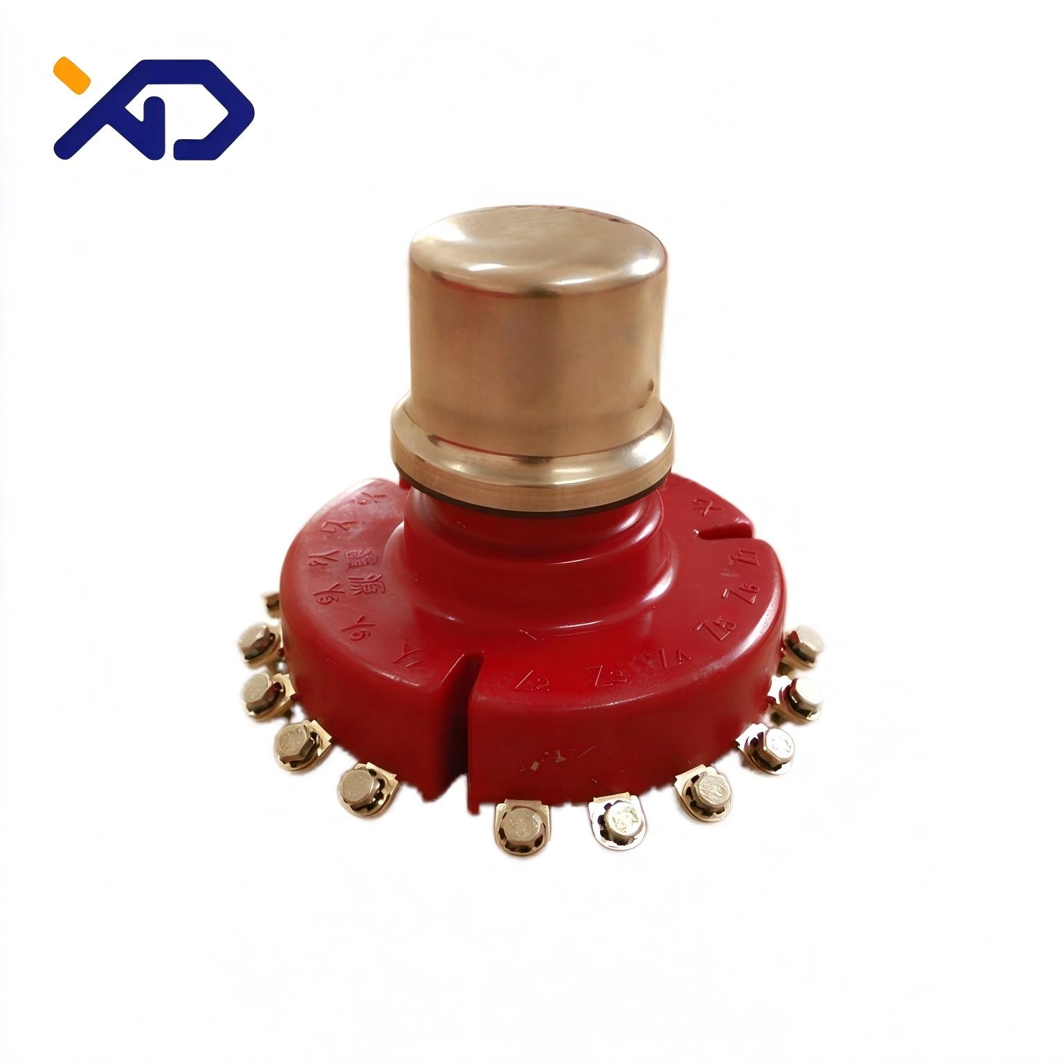
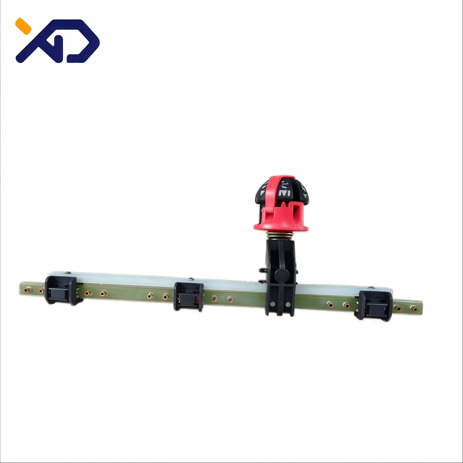
Full Range of Non-Excitation (Off-Circuit) Tap Changers: Disk Type WSPⅡ / Bar Type WSTⅡ / Export-Specific Magnetic-Strip Type, 10–24 kV, 30–250 A, 18 Models
Product Overview
A non-excitation tap changer (off-circuit tap changer) is the voltage-regulating device of an oil-immersed transformer: with the transformer de-energized, turning the operating head changes the winding tap connection and adjusts the HV ratio so the output voltage matches the grid. Tianjin Xingda offers three series with 18 models, covering 50/60 Hz and 10/24/35 kV voltage classes:
① WSPⅡ non-excitation disk-type tap changer — new structure, new materials and new technology: strong hand feel, flexible rotation, accurate positioning, good sealing performance and low contact resistance; cage (disk) type moving contacts, three-phase 63/125/250 A, fixed directly on the cover or wall of the transformer box; 6 models. ② WSTⅡ non-excitation bar-type tap changer — bar-type (rail) contact construction with middle regulating position, three-phase 63/125/250 A, mounting rail fixed directly on the cover or wall; 6 models. ③ Export-specific non-excitation magnetic-strip tap changer — compact magnetic-strip construction for export markets, 24 kV class 30/63 A, with neutral-point or middle regulating positions; 6 models.
Installation & fitment: disk types use a Φ43 tank-cover opening with M6 fixing screws; bar types use the same Φ43 opening with M6/M8/M10 bolts by current step (M8×30 bolts provided by the transformer factory); magnetic-strip types use a Φ20+1 opening, with Φd1/Φd2 as the lead solder-joint holes. Terminals are solder-joint connected; the operating head sits above the cover with a positioning ratchet for accurate step location.
Model naming: series – rated current/rated voltage – contacts×steps (e.g. WSPⅡ 250/10-4×3 = 250 A, 10 kV, 4 contacts 3 steps, ±5%; 6×5 = 6 contacts 5 steps, ±2×2.5%). All dimensions listed are for our regular products; custom designs are available per customer drawings.
Models & Specifications
Table 1 | WSPⅡ disk-type non-excitation tap changer (10 kV, 63–250 A, 6 models)
| Model | Rated current (A) | Rated voltage (kV) | Regulation range | Phase | Regulating part | H | H1 | D1 | D2 | Md | Tank cover opening |
|---|---|---|---|---|---|---|---|---|---|---|---|
| WSPⅡ 63/10-4×3 | 63 | 10 | ±5% | 3 | middle | 150 | 75 | 170 | 80 | M6 | Φ43 |
| WSPⅡ 125/10-4×3 | 125 | 10 | ±5% | 3 | middle | 150 | 75 | 175 | 80 | M6 | Φ43 |
| WSPⅡ 250/10-4×3 | 250 | 10 | ±5% | 3 | middle | 160 | 85 | 220 | 80 | M6 | Φ43 |
| WSPⅡ 63/10-6×5 | 63 | 10 | ±2×2.5% | 3 | middle | 150 | 75 | 197 | 80 | M6 | Φ43 |
| WSPⅡ 125/10-6×5 | 125 | 10 | ±2×2.5% | 3 | middle | 150 | 75 | 200 | 80 | M6 | Φ43 |
| WSPⅡ 250/10-6×5 | 250 | 10 | ±2×2.5% | 3 | middle | 160 | 85 | 280 | 103 | M6 | Φ43 |
※ D1 = contact-cage outer diameter, D2 = insulation-cylinder related diameter. The series description also covers 35 kV and 400 A (not listed in the catalogue tables; available on request).
Table 2 | WSTⅡ bar-type non-excitation tap changer (10 kV, 63–250 A, 6 models)
| Model | Rated current (A) | Rated voltage (kV) | Regulation range | Phase | Regulating part | H | H1 | L | L1 | L2 | L3 | L4 | l | Md | Tank opening |
|---|---|---|---|---|---|---|---|---|---|---|---|---|---|---|---|
| WSTⅡ 63/10-4×3 | 63 | 10 | ±5% | 3 | middle | 180 | 100 | 376 | 143 | 122 | 58 | 97 | 24 | M6 | Φ43 |
| WSTⅡ 125/10-4×3 | 125 | 10 | ±5% | 3 | middle | 180 | 100 | 441 | 158 | 147 | 58 | 105 | 29 | M8 | Φ43 |
| WSTⅡ 250/10-4×3 | 250 | 10 | ±5% | 3 | middle | 205 | 120 | 486 | 173 | 162 | 68 | 120 | 34 | M10 | Φ43 |
| WSTⅡ 63/10-6×5 | 63 | 10 | ±2×2.5% | 3 | middle | 180 | 100 | 520 | 191 | 170 | 58 | 97 | 24 | M6 | Φ43 |
| WSTⅡ 125/10-6×5 | 125 | 10 | ±2×2.5% | 3 | middle | 180 | 100 | 615 | 216 | 205 | 58 | 105 | 29 | M8 | Φ43 |
| WSTⅡ 250/10-6×5 | 250 | 10 | ±2×2.5% | 3 | middle | 205 | 120 | 690 | 241 | 230 | 68 | 120 | 34 | M10 | Φ43 |
※ L = full length of the mounting rail, L1 = distance from operating-mechanism centre to rail end, l = contact pitch; M8×30 fixing bolts to be provided by the transformer factory.
Table 3 | Export-specific magnetic-strip non-excitation tap changer (24 kV, 30/63 A, 6 models)
| Model | Rated current (A) | Rated voltage (kV) | Phase | Regulating part | H | L | L1 | l | Φd1 | Φd2 | Tank opening |
|---|---|---|---|---|---|---|---|---|---|---|---|
| WSTⅢ 30/24-5×5G | 30 | 24 | 3 | neutral point | 75 | 390 | 40 | 18 | Φ3.1 | Φ5.2 | Φ20+1 |
| WSTⅢ 60/24-5×5G | 63 | 24 | 3 | neutral point | 75 | 390 | 40 | 18 | Φ5.1 | Φ7 | Φ20+1 |
| WSTⅡ 30/24-6×5G | 30 | 24 | 3 | middle | 75 | 455 | 55 | 18 | Φ3.1 | Φ5.2 | Φ20+1 |
| WSTⅡ 63/24-6×5G | 63 | 24 | 3 | middle | 75 | 455 | 55 | 18 | Φ5.1 | Φ7 | Φ20+1 |
| WSTⅡ 30/24-8×7G | 30 | 24 | 3 | middle | 75 | 565 | 55 | 18 | Φ3.1 | Φ5.2 | Φ20+1 |
| WSTⅡ 63/24-8×7G | 63 | 24 | 3 | middle | 75 | 565 | 55 | 18 | Φ5.1 | Φ7 | Φ20+1 |
※ Φd1/Φd2 are the lead solder-joint holes; suffix G = export specific. Regulation ranges follow the naming rule (5×5 = 5 steps, 6×5 = 6 contacts 5 steps, 8×7 = 8 contacts 7 steps).
Which Series to Choose
| Application | Recommended series | Notes |
|---|---|---|
| Standard 10 kV distribution transformers (±5%, 3 steps, e.g. S11/S13) | WSPⅡ 4×3 | Most compact disk construction, D1 170–220, Φ43 cover opening |
| 10 kV units requiring ±2×2.5% 5-step fine regulation | WSPⅡ / WSTⅡ 6×5 | Disk type on the cover, bar type on the wall — either works |
| Larger 250 A units with flexible contact-rail length | WSTⅡ bar type (L 376–690) | Mounting rail suits wall layout; M8/M10 by current step |
| Export 24 kV units (pad-mounted substations, export distribution transformers) | WSTⅢ / WSTⅡ 24 kV magnetic-strip type | Neutral-point or middle regulation, Φ20+1 opening, 30/63 A |
| One-stop procurement | Any series + XD bushings / breathers | Same factory — complete the transformer in one order |
Why Xingda
The non-excitation tap changer is an XD self-manufactured transformer accessory: disk, bar and magnetic-strip constructions, 18 models with full tooling, covering 50/60 Hz, 10–24(35) kV and 30–250 A — tap changers, bushings and breathers can be sourced from the same factory in a single order. The disk series adopts new structure, materials and technology with strong hand feel, flexible rotation, accurate positioning, reliable sealing and low contact resistance; rail length, contact pitch and regulating position (neutral point / middle) of the bar and magnetic-strip series can be customised to the customer's winding drawing, with solder-joint hole positions and tank openings per the tables — drill, mount and connect.
Categories
Contact Us
Contact: Tianjin Juyida Technology Co., Ltd
WhatsApp: +86 13662056855
Tel:
E-mail: solomon20210701@tjxddq.com
Add: Unit‑101, Workshop 3, Bozhong Automobile Industrial Park, No.5 Xianghui Road, Intersection of Xianghui Road and Gaoying Road, Beizhakou Town, Jinnan District, Tianjin, China